Analysis of GPS Design Problems in Portable Navigation Devices
It is well known that if design engineers lack an understanding of basic hardware/RF design and electromagnetic interference (EMI) issues, then they design GPS in portable navigation devices (PNDs), personal digital assistants (PDAs), feature phones, and smartphone devices. Performance will be greatly reduced. The root cause of this is poor antenna design/selection or the inability to handle internal EMI interference.
This article refers to the address: http://
In the open sky environment, the GPS signal power level is nominally -125dBm. If you use an analogy, this is equivalent to a person in Finland looking at a 60W light bulb that is lit in Japan (if you can see it) . The GPS signal level is about 160dB lower than the 1W (+30dBm) GSM transmitter, so we often say that it is a very weak signal, almost no error in the receiver design.
The -125 dBm signal level substantially corresponds to an SNR (Signal to Noise Ratio or C/No) of 50 dBHz. Poor antenna design and EMI issues can reduce SNR by 15-20dB, which means the maximum SNR is only 30-35dBHz. Such low SNR has a large impact on performance, as decoding of satellite data will become extremely difficult. The user's feeling is that the start-up time (TTFF) is very long, and the overall performance is extremely poor, such as position jump or speed drift, and even worse, it is impossible to locate at all.
Antenna design
One of the criteria for selecting a GPS antenna in a portable device is size, especially for feature phones and smartphones with limited size. Most commonly used antennas are GPS patch antennas because they are relatively easy to tune and perform better.
The GPS L1 signal is an RHCP polarized signal with a frequency of 1.575 GHz and a wavelength of 19 cm. Such wavelengths obviously require large antennas unless they are made electronically shorter. Such antennas are typically fabricated from ceramic materials of <r>1. The higher the ?r, the smaller the device can be made. However, increasing the ?r affects the radiation efficiency of the antenna, and the effect is greater when a small chip device is mounted on a small ground plane. Such a small antenna will become linearly polarized instead of right-handed circularly polarized (RHCP), thus causing a 3dB polarization loss. The experience with chip antennas is as large as possible, not only the device itself, but also the ground plane underneath the device. Nothing is better than mounting a 25x25mm chip on a 70x70mm ground plane, but this is clearly not a viable option for portable devices, so a smaller antenna must be chosen.
Installing a 10x10mm chip device on a 10x10mm ground plane is a bad antenna option. Although this antenna is small and convenient, the total loss will be about 10dB for the above reasons, so that the maximum SNR is only 40dBHz, which is not EMI interference. Case.
Fastrax offers a wide range of antenna designs for users, and the company has even designed custom antennas for a variety of projects, including loop antennas to Helical antennas.
EMI problem
From a GPS perspective, EMI is a harmful broadband noise on GPS frequencies. EMI often occurs in portable devices. Interestingly, although EMI noise is usually lower than any EMC requirement, it is enough to interfere with GPS signals.
Importantly, EMI increases the noise level at the GPS frequency, which ultimately leads to a reduction in SNR. At the GPS receiver, there is no way to reduce EMI, and EMI must be suppressed at the source. There are two ways for EMI to enter the receiver, one is conduction (through the wire) and the other is radiation (through the antenna). Radiated EMI is usually worse.
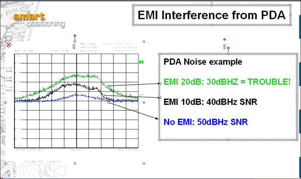
Radiated EMI in portable devices is typically within 10-20 dB, which will reduce the SNR of the same value, so it is important to minimize EMI to maintain good GPS performance.
Figure 1 shows a typical EMI case (Taiwan PDA). The user can only obtain an SNR of 30 dBHz without any modification. Fastrax can help designers locate the source of EMI and reduce it to near zero.
Basically, all portable devices tested by Fastrax with high-speed CPUs and high-speed memory buses have EMI issues. However, if the hardware engineer can keep the following four points in mind, you can avoid the most typical system design errors and effectively suppress EMI. The four points are:
Use a uniform [d1] ground plane
Use RF shield
Minimize the number of wires
Avoid clock harmonics at GPS frequency points
Our goal is to use the Faraday box on the PCB and the device itself to keep the noise inside.
In design, the most common mistake is that the hardware designer splits the ground plane on the PCB, an analog ground, a digital ground, a radio frequency ground, and so on. This is because many e-books are still encouraging the use of separate ground planes! This is completely wrong. There is no better way to share a ground plane than all electronic devices. If it is necessary to divide, according to the radio frequency duality theorem, the open circuit of the ground plane will radiate noise as a small antenna.
The second biggest mistake is that the electronics are not shielded, which means the device itself will radiate noise. This problem can be easily solved by placing all the electronics in the RF shield.
Another potential source of EMI is wires, such as the wires of speakers and microphones, which also radiate EMI like an antenna. A good suggestion is to add 18pF decoupling capacitors to these wires.
Finally, avoid clock harmonics falling into the GPS band. For example, if the clock frequency is 7.5MHz, then its 210th harmonic will be exactly the frequency of the GPS.
From the perspective of solving EMI problems, following these simple EMI guidelines can help users achieve better hardware design.
F1:
F2: Avoid splitting the ground plane
F3: Use RF shield [d2]
Fiber Patch Cords, Fiber Optic Patch Cord, Fiber Optic Patch Cables, Optical Patch Cord
NINGBO YULIANG TELECOM MUNICATIONS EQUIPMENT CO.,LTD. , https://www.yltelecom.com