Design and Implementation of Intelligent Sound Control System for TV Set
Label: Remote Launch MIC
This article refers to the address: http://
With the increasing number of TV channels, the drawbacks of traditional TV remote control methods are becoming more and more obvious. It requires a large number of TV stations to design a color TV intelligent voice control channel selection system for the tone recognition chip TSG410, which can better solve the memory channel problem. Especially for the friends of the column, it has a special meaning.
The system does not make any changes to the color TV. On the basis of retaining the original remote control function, voice control is selected. The main functions are as follows:
Switching TV: The TV is connected to the power supply, and the operator issues a “power on†command to turn on the TV; when the operator issues a “shutdown†command, the TV is turned off;
Selection function: The operator wants to watch the program of XX TV station. As long as the command of “XX station†is issued, the TV will automatically jump to the station.
Identification of the master function: day to prevent the operation, the system can only be recorded in the command sample operator's voice sensitive, other people's commands including the TV sound are invalid.
Other functions: It has functions such as TV volume and screen brightness adjustment suitable for voice control.
1 system design
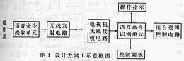
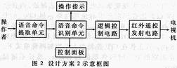
We initially considered two design options (see Figures 1 and 2), each with advantages and disadvantages. The first circuit is shortcoming: the circuit is a bit more complicated, and the necessary changes to the TV's channel control circuit (of course this is not a problem for TV manufacturers); the advantage is: only one wireless The microphone can be voice-activated and does not have to be aimed at the TV, even in another room. The advantage of the second circuit is that it does not have to make any changes to the TV control circuit of the TV set; the disadvantage is that all circuits can only be powered by the battery, and the chip selection should consider the power consumption and the working voltage. Since the infrared remote control is used to control the TV, the system must be aligned with the TV to function properly. Taking into account various factors, we recognize that the second design is practical.
2 Introduction to each function module
2.1 voice command extraction unit
The voice command provides the unit (as shown in Figure 2) in the background of television voice and other noise, completes the extraction of the operator voice command function, the schematic diagram of which is shown in Figure 3.
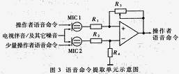
The MIC uses an electret microphone, which has the advantages of simple structure, light weight, small size, wide frequency response, good fidelity, etc., but the sensitivity is low, and an amplifier must be added. Since the output impedance can be on the order of 10 8 Ω, it must be impedance-converted before it can be used with the amplifier. The amplifier uses a differential amplifier circuit, one electret microphone faces the caller, and its output sinks the forward input of the amplifier; the other electret microphone is facing away from the sender, and its output is connected to the negative input of the amplifier. . Since the two microphones are located at substantially the same position relative to the television and other noise sources, the interference input through the two can be approximated to be the same. However, considering the directionality of the microphone, the operator's voice command sent by the former is much larger than the latter, and proper selection of each resistance value can offset various interferences. The amplifier uses an op amp (OPAmps) MAX495 (single power supply +2.7 to +6V).
2.2 Speech recognition unit
The speech recognition unit is mainly composed of TSG410 and non-volatile SRAM, and is roughly constructed as shown in FIG. 4 below.
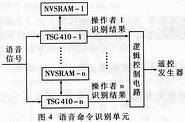
The speech recognition function is completed by a dedicated voice chip TSG410, which is a novel and fully functional speech recognition integrated circuit. It is fabricated in a CMOS LSI manufacturing process and contains all the circuitry required for speech recognition other than SRAM, such as CPU, A/D converter, ROM, voice amplifier, compressor, filter, oscillator and interface circuit. . The TSG410 is available in dual in-line and patch-mount packages and operates in both CPU and manual modes. The response time of speech recognition is typically 300ms per day and no longer than 600ms.
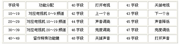
The recognition capacity is large, and up to 40 fields can be identified, and the segmentation mode is flexible. For the convenience of CPU management, 40 fields are divided into four groups, numbered from 1 to 4, and each group has 10 segments. Thus, the first field number is 10, the second one is 11, the third is 12... and so on, and the 40th field number is 49. In the operation display, the ten digits display the group number, and the single digits display the serial number. Therefore, when establishing a speech sample, attention should be paid to the conversion relationship between the digital display and the TV selection frequency, so that the voice command and the control result do not correspond. The function assignments of each segment are shown in Table 1.
The length of each field of the TSG 410 can be selected between 0.9s and 1.92s. According to the normal person's speaking speed, 2 to 4 words are spoken per second. If 0.9s is selected, each command field should be 1~3 words, and the maximum capacity is 8 Chinese characters when 1.92s is selected, but the identifiable field is selected. The number is reduced to 20. We choose a segmentation method for glue, and the voice command should be less than 3 words. Therefore, the TV channel selection command adopts the "local" naming principle, such as: Shandong, Shanghai, etc., the central station can directly call "one Taiwan", "two Taiwan", and so on. The greater the difference in voice commands, the less likely it is to be misidentified. To make the system work properly, you must first establish a voice sample. To prevent the voice sample from being lost due to power loss, the SRAM selects a non-volatile SRAM with a built-in power-down protection battery, that is, NVSRAM (non-volatile SRAM), such as HK1125. Its data can be stored for more than 10 years, the usage is the same as ordinary RAM.
In general, it is sufficient to leave 30 pre-selected channels. In fact, it is possible to use a plurality of TSG410s to perform channel number and allow the number of operators to expand to meet various needs, or to use the TSG410 to operate in a CPU control mode. At this time, the identification capacity is not limited by the 40 field, but it is necessary to add a single-chip microcomputer (such as 8031) for control.
2.3 Control Panel
In order to be able to enter the field number to create a voice sample, the RSG 410 is equipped with an external keyboard scan circuit. The input and output ports of the row and column signals are carried by S1 to S3 and K1 to K3 of the chip. Such a three-column, four-line keyboard has a total of 12 buttons, ten of which are defined as: 0 to 9 number keys, one defined as: voice sample setup key (TRN), one defined as: voice sample clear key (CLR). Since the control panel is only used when creating voice samples, to prevent misoperation, the 12 buttons should be brightly sealed with plastic.
2.4 operation indication circuit
The operation indicating circuit is composed of two digital tubes and a decoding driving circuit CC4558. In the system, the operation indication circuit functions to display the stored field number when the voice command sample is established, and the processing report for displaying the recognition result and the chip recognition result when the voice command is recognized.
2.5 logic control circuit
The entire logic control circuit is shown in Figure 5. The TSG 410 outputs the recognition result through D0 to D7, and must perform the necessary base code before it can be used to control the infrared emitter behind. In the remote control system of the television, the remote control transmitter emits various pulse coded information in infrared mode through buttons. In particular, it is important to note that the transmit code must be identical to the original to be compatible. When using an electronic switch circuit to simulate a manual button, the switch-on time and the time interval between the two buttons must be considered to prevent signal loss and "string" and "bundle" phenomena. Under normal circumstances, the time for scanning all the keys is less than 10~20ms, and the time to touch the button is also less than 100ms. Therefore, after any button is pressed, there will be multiple scan signals passing, there is no signal loss problem. . The so-called "string key" means that after one key is pressed, another key is pressed, and the "parallel key" is to press two keys simultaneously. The root cause of these two types of error operations is that the remote command code of each button takes a certain amount of time to complete (usually around 100ms), so try to eliminate it. This is a difficult point when we design the logic control circuit, which is solved by pulse stretching (>40ms) and pulse delay circuit (>120ms).
2.6 remote control transmitting circuit
The infrared remote control transmitter is mainly composed of three parts: one is the keyboard matrix, the other is the transmitting special integrated circuit, and the third is the amplification driving and the infrared emitting part. This circuit is related to the specific model of the TV, and the appropriate dedicated infrared transmitting circuit can be selected according to the TV brand.
It should be noted that since the infrared transmission and receiving circuits of different brands of TVs are different, it is only effective for compatible TVs.
This Bluetooth Karaoke Microphone Speaker is designed for music singing fans. This Karaoke Microphone Speaker is the most wonderful microphone. This portable Microphone speaker combines microphone, KTV echo and louder speaker in one. The Good Speakerphone for Home Office connects Mobile phone/tablet/computer by Bluetooth easily, you can enjoy singing at anywhere and anytime. With cable, it supports singing recording at the same time. At home party, this Portable Karaoke Speaker can increase the enjoyment of life, you can sing song freely with your family and friends, and you can use this Wireless Microphone systems record your songs and submit to some sing APP to get high popularity. Also people can use this Bluetooth Conference Speakerphone make speech practice to add your public presentation ability. It is a good present for your family and friends.


Microphone Speaker
Microphone Speaker,Portable Mic System,Portable Mic Speaker System,Portable Wireless Mic System
Shenzhen New Wonderful Technology Co., Ltd. , https://www.sznewwonderful.com