Design of MEMS-based automotive laser projector
The display and information systems in the car are very rich, surrounded by us, some information is very important, some for comfort or entertainment, and some just provide information, which is valuable, but not necessary. As a driver, what we need most is critical data about the car's working conditions – and it's real-time.
Automakers use a variety of technologies to provide drivers with such critical information, including discrete LEDs, dashboards and liquid crystal display technology. Although the model of each car is different, the way information is provided is very consistent, and almost every occupant can quickly adapt to and get information from unfamiliar models. In addition, these data and information can also be virtually projected into the line of sight of the driver in front of the vehicle using a heads up display (HUD) system. With the continuous development of display technology, HUD has become very popular in luxury cars. With the reduction of cost, size reduction and performance improvement, these HUD systems are also being adopted by mid-range cars and will soon be popularized in economy cars.
The latest HUD technology uses mobile MEMS mirrors and color lasers, so-called miniature laser projectors. These laser projectors offer the advantages of infinite focus, clear sunlight, superb color saturation and small size, making them ideal for automotive infotainment systems.
This paper proposes a new scheme using a miniature laser projector by analyzing the modern HUD technology in the automotive field. The integrated "bridge chip" solution uses a high-performance three-channel laser driver that reduces size, cost, and design complexity compared to older TFT, CRT, and DLP technologies, all thanks to the laser.
HUD technology foundation
At the heart of the latest HUD technology is a miniature laser projector (Figure 1), a small MEMS imaging system that projects a pixel array onto almost any surface. Micro-laser projectors do not use radiation technology (TFT and CRT), but instead emit a bundle of colored light to draw images, meters and indicators. The beam scans a raster image similar to a CRT TV. Each pixel is produced by a combination of chromaticity and brightness of the three primary colors (see Figure 1).
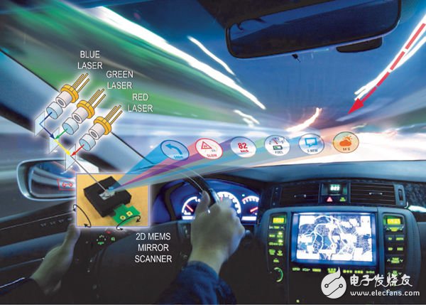
Figure 1. The core of the pico projector is the R, G, and B lasers, as well as the moving MEMS mirror.
Using the MAX3601 laser driver's integrated 8-bit DAC, each pixel produces 24-bit full-color RGB colors, resulting in 16 million unique colors. Because the laser emits each color at a very different frequency, it is brightly colored and can be "oversaturated" to attract the driver's attention. In the woods or jungle environment, the green color is deliberately highlighted to highlight.
The combined beam is sent to a scanning MEMS mirror chip which produces a scan line by horizontal scanning and then longitudinally ramped to combine the scan lines into a display surface. The resulting high-definition image is refreshed at 60 Hz and is always in focus – another advantage of laser technology, especially for curved automotive windshields.
The challenge of driving micro projectors
In a cathode ray tube (CRT), each scan line starts from the left and is quickly returned to the start of each line using a flyback method (Figure 2). With modern digital technology, the miniature laser projector scans odd lines in a forward direction and scans even lines in a reverse manner (Figure 3).
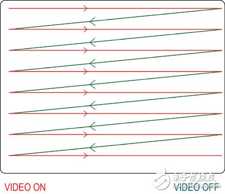
Figure 2. During the blanking of the CRT, the beam is turned off and the retrace returns to the next line.
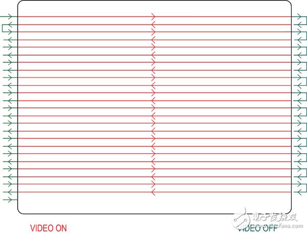
Figure 3. For a pico projector, the laser turns on when drawing each line from left to right; then turns off in the inactive video area that falls vertically; when the active video is drawn from right to left, the laser turns on again.
Another difference between CRT and microlaser projector technology is the timing variation, which depends on the position of the pixel on the horizontal scan line. Because of the MEMS technology, the mirror must accelerate and decelerate at the beginning and end of each line. Due to the inertia of the MEMS mirror, it slows down before reaching each end, thus forcing pixels sent with a constant pixel clock to "push up" at the end. If left uncorrected, this pixel sticking phenomenon will show high edge brightness and coordinate distortion from left to right (Figure 4).
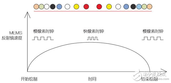
Figure 4. The upper row of colored dots represents the MEMS pixel space. Since the moving mirror is mechanical, both acceleration and deceleration take time. This angular velocity distortion is compensated in a clever way.
One way to correct the bunching phenomenon is to create virtual pixels and insert sub-pixels in each segment of the scan line. In the middle of the scan line, the MEMS mirror has the fastest scan rate, where the sub-pixels are transmitted at a rate of one sub-pixel per virtual video clock. On the edge, a sub-pixel is sent every 3, 4 or 5 clocks.
![]()
Figure 5. On the left edge, the pixels are interpolated - 1 pixel per 4 subpixel clocks; in the middle segment, each subpixel clock is 1 pixel.
The complexity of traditional laser projector design
Controlling each high-speed laser pixel requires the device to quickly turn pixels on and off, plus many advanced interfaces, resources, and functional circuitry (Figure 6). The MAX3601 RGB laser driver (Figure 7) is capable of modulating pixel edges in 1 ns, making it ideal for this application. Turning off the laser pixels is extremely challenging due to the high capacitive and inductive load of the laser. Maxim's unique Pixel-Off Assist feature makes it possible to turn off the edge rate in 1ns. The three-channel DAC operates at 250MHz and above to ensure video speed in HD resolution.
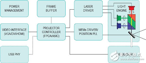
Figure 6. The traditional architecture of a miniature laser projector SoC requires many advanced interfaces, resources, and functional circuits.
LCD, DLP and other backlighting technologies face great challenges at night and in tunnel conditions, and backlight leakage can create shadows or ghosts. This problem does not exist with laser projectors, because the laser illuminates each pixel with a front light method. Since the laser projector increases the illumination pixel by pixel, the power is always less than 100% fully open except for the laser bias current. The power can be turned off during the blanking period and when the pixel is black. In this way, for a full black scene, the power consumption is reduced to 80mW. The MAX3601 features a multiplying DAC that modulates the light output power from 1 lumen in the dark to 30k lumens in the sun.
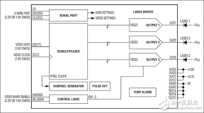
Figure 7. The integrated MAX3601 three-channel laser diode driver is flush with the bridge chip design to form a highly integrated solution. See below for a discussion of bridge chip design.
Continuous monitoring of laser color to ensure color consistency over a wide temperature range and to ensure laser condition safety. Color sensors are also used to compensate for daylight, shadow or nighttime conditions. Because the laser is always in focus, complex and expensive optics do not take up valuable space in the optical engine. Therefore, the laser projector is very suitable for the demanding requirements of small cars. Since the current HUD architecture uses 7 or more devices for rendering colors, the space saved by this solution becomes especially valuable.
Bridging technology: a bridge chip supports real-time and critical processing
In traditional laser projectors, the video laser controller SoC has almost the same power as the host SoC controller, and also has a similar size video frame buffer and GPU functions. Micro projectors only account for a portion of the processor bandwidth when performing critical tasks in real time. Traditional designs send data from the video frame buffer to the frame buffer of the pico projector processor and then parse it to the MEMS mirror line by line, which is cumbersome and inefficient.
In order to eliminate this redundancy and again balance the cost, power consumption and load of each critical component, the bridge chip provides a reasonable compromise.
The micro laser projector streamlines the data stream by using a bridge chip (Fig. 8) for efficient processing. The two video frame buffers are reduced to one. The real-time task is handled by the bridge chip, which no longer consumes a large amount of system load interruption, thereby reducing the SoC load and reducing the cost and power consumption. The SoC's GPU handles FIFO-LIFO scan line inversion memory addressing and compensates for MEMS inertial motion. The workload is balanced.
In theory, then, where do you start? Let's first look at the projector's SoC capabilities and then decide how to package these features. Both the host SoC processor and the video processor have a 6MB frame buffer, so we can save memory and replace it with a few line buffers. This requires tight timing between the high speed video input and the slower line rate of the MEMS mirror; this is especially important for supporting the different resolutions required for HUD applications. The bridge chip ensures that the line buffer is always fully loaded, while also checking that the host SoC is turned off or that few critical functions are active to save system power.
Interrupting the SoC to handle general real-time tasks and service-predictable interrupts results in higher power consumption of the SoC during idle periods. This is very wasteful because the bridge chip is more suitable for processing real-time tasks, so it can be said that the bridge chip maximizes system efficiency.
The host SoC is ideal for handling GPU tasks such as scaling, color correction, white balance, reverse distortion (to compensate for the pincushion effect caused by the windshield's curved surface or flying point architecture), and to send data to fill the line buffer of the bridge chip. For SoCs with a few lines of code, reversing memory addressing from left to right and right to left is a simple task. The SoC will preprocess the data and send it to the bridge chip without knowing the MEMS timing requirements.
The micro-microprocessor or state machine built into the bridge chip can handle simple auxiliary tasks, giving designers the flexibility to add custom features.
The four-chip solution built around the bridge chip forms a highly integrated, programmable microlaser projector that connects to standard video interfaces such as HDMI and VGA. This solution handles all projector related tasks. But can we further compress the design?
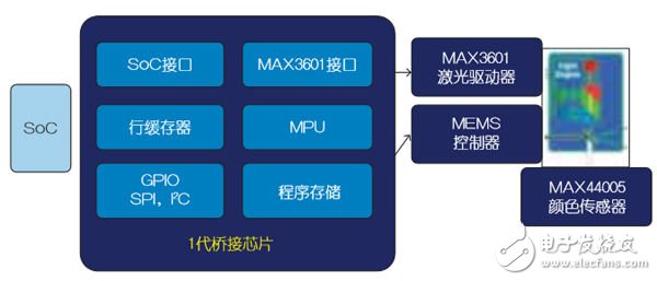
Figure 8. A four-chip microlaser projector solution can be implemented with a bridge chip, but a more integrated solution is better.
For applications that require higher levels of integration, such as mobile phones and other small consumer devices, bridge chips can be combined with other features. For example, we can design a programmable bridge chip that supports distance detection, barrel distortion compensation, mirror acceleration and deceleration compensation, and brightness, color, and vibration stabilization. It is also desirable to have hardware circuitry that supports anti-shake, sawtooth raster scanning, byte video data alignment, variable resolution, and brightness control and power management. Let the processor-driven core run hardware algorithms in software that are fast enough to refresh almost jitter-free images. Now, the previous four-chip solution can be reduced to one chip (Figure 9).
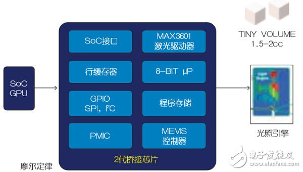
Figure 9. The new generation of highly integrated bridge chips is reduced to a single-chip miniature laser projector solution.
in conclusion
Micro laser projectors are gradually being embedded into smartphones, tablets, laptops, wearable computers, and automotive HUD displays. In 2013, more than 500,000 vehicles were equipped with HUDs, and the growth rate is expected to reach 2 to 20% to 30% in the next five years. Therefore, it is completely understandable that OEMs require HUD space and cost savings. The highly integrated bridge chip, as shown in Figure 8 and Figure 9, will greatly reduce the load on the host processor, saving space, power, chip count, and processing resources required.
The CPU-centric HUD micro laser projector bridge chip solution supports high-quality peripheral integration and fast processor so that algorithms can be executed in software. The use of bridge chips reduces hardware, reduces power consumption and complexity, and provides flexibility for implementing new ideas and methods for HUD.
In the future, miniature laser projectors will feature a flying point architecture that extends functionality to 3D camera and gesture control applications. In late 2014, these features will be available in PCs and tablets, followed by HUD devices that will be widely used in cars.
In the near future, the driver can adjust the radio volume or switch to different channels by simply waving his hand in front of the center console; both eyes will observe the road ahead through the laser HUD to ensure safety. The highly integrated miniature laser projector bridge chip and reference design will provide companies with the means to quickly adopt this technology, be creative and profitable.
Sensor Dustbin Automatic Dustbin
Sensor Dustbin Automatic Dustbin,Automatic Sensor Recycling Dustbin,Stainless Steel Sensor Automatic Dustbin,Automatic Sensor Dustbin
NINGBO ZIXING ELECTRONIC CO.,LTD. , https://www.zixingautobin.com