Stepper motor driver wiring diagram
A stepper motor driver acts as an actuator that converts electrical pulses into angular displacement. When the stepper driver receives a pulse signal, it moves the stepper motor to rotate a fixed angle (referred to as the "step angle") in a predetermined direction. The rotation occurs incrementally at a fixed angle. The angular displacement can be precisely controlled by adjusting the number of pulses, thus enabling accurate positioning. Additionally, the speed and acceleration of the motor can be regulated by manipulating the pulse frequency, which helps control both the speed and the positioning.
Stepper motors are categorized based on their structure. They are also known as pulse motors and include various types such as reactive stepping motors (VR), permanent magnet stepping motors (PM), and hybrid stepping motors (HB).
(1) Reactive stepping motor: Also called inductive, hysteresis, or magnetoresistive stepping motor. Both the stator and rotor are made from soft magnetic materials. Large magnetic poles evenly spaced around the stator have multi-phase excitation windings, while the stator and rotor are both equipped with evenly distributed small teeth and slots. Upon energization, torque is generated due to changes in magnetic permeability. Typically available in three, four, five, or six phases; capable of producing large torque output (high power consumption, currents up to 20A, high driving voltage); small step angles (minimum 10'); no positioning torque when powered off; low internal damping in the motor, resulting in longer oscillation times during single-step operations (at very low pulse frequencies); and higher starting and running frequencies.
(2) Permanent magnet stepping motor: The rotor is typically made from permanent magnet material, while the stator is made from soft magnetic material and has multi-phase excitation windings. There are no small teeth or slots around either the stator or rotor. Once energized, the interaction between the permanent magnets and the stator's current magnetic field generates torque. Usually available in two-phase or four-phase configurations; produces smaller output torque (lower power consumption, currents typically below 2A, driving voltage 12V); larger step angles (for example, 7.5°, 15°, 22.5°, etc.); holding torque when stationary; lower starting and running frequencies.
(3) Hybrid stepping motor: Also referred to as permanent magnet-reactive or permanent magnet-inductive stepping motor, this combines the benefits of both permanent magnet and reactive types. The stator is identical to that of a four-phase reactive stepping motor (except the two magnetic poles of the same phase are opposite, with N and S polarities of the windings on the two magnetic poles being the same), but the rotor structure is more complex (it has a cylindrical permanent magnet inside, soft magnetic material on both ends, and small teeth and grooves around it). Typically available in two or four phases; requires both positive and negative pulse signals; produces larger output torque than permanent magnet motors (lower power consumption); smaller step angles than permanent magnet motors (typically 1.8°); positioning torque; higher starting and running frequencies; and represents the fastest-developing type of stepper motor.
Huaqiang Electronic Network has summarized several wiring methods for stepper motor drivers. Below are two methods along with their corresponding circuit diagrams:
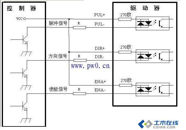
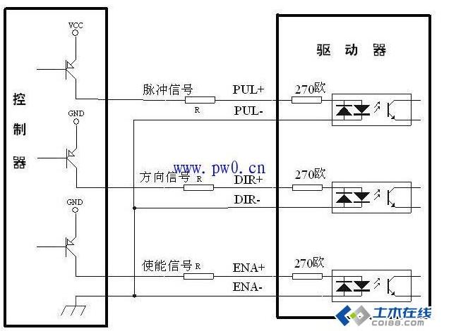
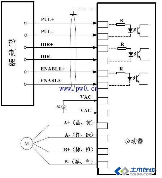
1. Common Anode Connection Method, Common Cathode Connection Method, and Differential Connection Method
Common Anode Connection

Common Cathode Connection

Differential Method

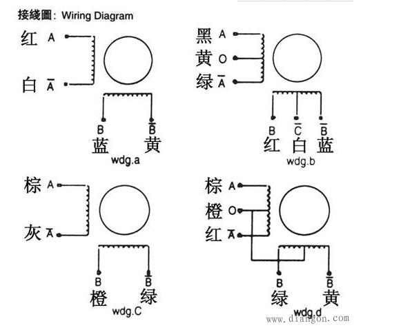
2. Wiring Methods for 4, 6, and 8-Wire Motors
High-Speed Mode for 4-Wire and 6-Wire Motors: The output current should be set equal to or slightly less than the motor’s rated current;
High-Torque Mode for 6-Wire Motors: The output current should be set to 0.7 times the motor’s rated current;
Connection Method for 8-Wire Motors: The output current should be set to 1.4 times the unipolar connection current of the motor;
Series Connection for 8-Wire Motors: The output current should be set to 0.7 times the motor’s unipolar connection current.

Low Frequency Inverter Charger
Low Frequency Inverter Charger
Have good environmental adaptability. Resistant to high temperatures, dust, stable output. Suitable for outdoor, vehicle, office space.
Low Frequency Inverter Charger,Low Frequency Inverter 24V,Low Frequency Inverter,Car Power Charger
SUZHOU DEVELPOWER ENERGY EQUIPMENT CO.,LTD , http://www.fisoph-power.com