Operational amplifier total output noise calculation for second-order systems
The circuit shown in Figure 1 below represents a second order system in which capacitor C1 represents the source capacitance, the stray capacitance of the inverting input, the input capacitance of the operational amplifier, or any combination of these. C1 causes a break in the noise gain, and C2 is a capacitor that must be added for stability.

Figure 1: Operational Amplifier Noise Model with Reacting Components (Second Order System)
Due to the presence of C1 and C2, the noise gain is a function of frequency and peaking at higher frequencies (assuming C2 is chosen such that the second order system is in a critically damped condition). As long as R1 & TImes; C1 = R2 & TImes; C2, a flat noise gain can be achieved. However, for current to voltage converters, R1 is typically high impedance, so this method does not work. In these cases, it is a bit complicated to maximize the signal bandwidth.
When a DC signal (B ground) is applied to input A, the gain (ie, low frequency noise gain) is 1 + R2/R1. At higher frequencies, the gain from input A to the output becomes 1 + C1/C2 (high frequency noise gain). Note that the closed-loop bandwidth fcl is the frequency at which the noise gain intersects the open-loop gain. When a DC signal (A ground) is applied to B, the gain is –R2/R1, where the high frequency cutoff point is determined by R2-C2. The bandwidth from B to the output is 1/2R2C2.
The current noise IN+ at the non-inverting input flows through R3, causing the noise voltage of IN+R3, which is the same as the noise noise of the op amp noise voltages VN and R3 (4kTR3), which is amplified by the frequency-dependent noise gain. The Johnson noise of R1 will be amplified in the 1/2R2C2 bandwidth range – R2/R1, and the Johnson noise of R2 will not be amplified at all, but will be directly connected to the output within the 1/2R2C2 bandwidth. The current noise IN– at the inverting input – only flows through R2, which causes a voltage of size IN–R2 at the output of the amplifier in the 1/2R2C2 bandwidth.
If we consider these six noise contributions, we will find that if R1, R2, and R3 are small, the effects of current noise and Johnson noise will be minimized, and the main noise will be the voltage noise of the op amp. As we increase the resistance, the voltage noise generated by Johnson noise and noise current will increase.
If the noise current is small, Johnson noise will replace the voltage noise and become the dominant noise contribution. However, Johnson's noise increases as the square root of the resistance increases, and the current-noise voltage rises linearly as the resistance increases. Therefore, as the resistance continues to increase, the voltage caused by the noise current will become the main factor. Whether the input is connected to Node A or Node B (the other is grounded or connected to other low-impedance voltage sources).
The noise contribution analyzed above is unaffected, which is why the in-phase gain (1 + Z2/Z1) appearing on the op amp voltage noise VN is called the "noise gain". The total output rms noise of the amplifier system needs to be multiplied by the corresponding gain and then integrated at the corresponding frequency, as shown in Figure 2 (below).
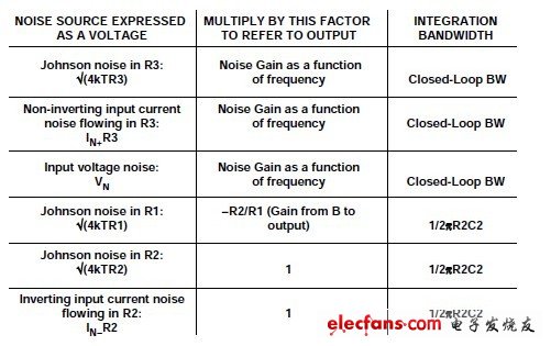
Figure 2: Noise source of the second-order system folded to the output
Then, the sum square root of all output contribution factors represents the total rms output noise. Fortunately, in most cases, proper assumptions and identification of major noise contributors can greatly simplify this complex and cumbersome process. The noise gain of a typical second-order system is shown in Figure 3 below. Although voltage noise integration can be easily accomplished in two steps, please note that due to peaking, the output noise caused by input voltage noise is mainly determined by the high frequency portion of the noise gain of 1 + C1/C2. This is the typical response type for second-order systems. Inverting input current noise, noise caused by R1 and R2 is only integrated over the 1/2R2C2 bandwidth.

Figure 3: Noise gain of a typical second-order system
Classical Crystal Chandelier is retro and classical style chandelier. The main materials usually have metal and different top crystals. These style always has a sense of hierarchy, full of rationalism. The big size of classical Crystal Chandelier are much applied to luxury house, like vintage, villa , church and so on.

Classical Crystal Chandelier
Classical Crystal Chandelier,Crystal Chandelier,Decorate Hanging Chandelier,Crystal Lighting
Zhongshan Laidi Lighting Co.,LTD , http://www.idealightgroup.com