Static Timing Analysis Basics and Application Serialization (3)
8. Assume that the signal of the front-end Flip-Flop changes from 1 to 0, and calculates the AT of the second Path end.
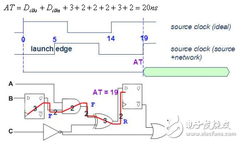
Figure twenty nine
9. Calculate the RT of the 2nd Path Endpoint
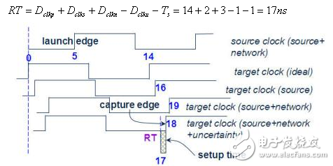
Figure 30
10. Assume that the signal of the front-end Flip-Flop changes from 0 to 1, and calculate the Slack of the second Path end. Slack is negative, so TIming is not satisfied.
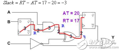
Figure 31
11. Assume that the signal of the former Flip-Flop changes from 1 to 0, and the Slack of the 2nd Path end point is calculated. Slack is negative, so TIming is not satisfied.
Integral 10 and 11, the TIming of the 2nd Path is not satisfied, and its Slack is -3.
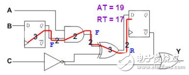
Figure thirty-two
12. Assume that the signal of the front-end Flip-Flop changes from 0 to 1, and calculate the AT of the third Path end.
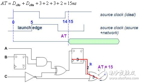
Figure thirty three
13. Assume that the signal of the front-end Flip-Flop changes from 1 to 0, and calculate the AT of the third Path end.
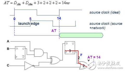
Figure thirty four
14. Calculate the RT of the Path End of Article 3
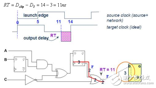
Figure 35
15. Assume that the signal of the pre-Flip-Flop changes from 0 to 1, and calculate the Slack at the end of the third Path. Slack is negative, so TIming is not satisfied.
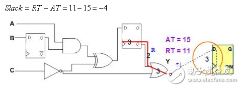
Figure 36
16. Assume that the signal of the former Flip-Flop changes from 1 to 0, and the Slack of the 3th Path end point is calculated. Slack is negative, so Timing is not satisfied.
Integral 15 and 16, the third Path Timing does not meet the specifications, and its Slack is -4.
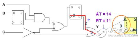
Figure 37
Based on the above analysis results, the timing of this circuit does not meet the specifications, and its Critical Path is Path3 and Slack is -4.
Round Hole Pin Connector,Gold-Plated Round Hole Female Header,Dedicated Round Hole Pin Header,Single Row Round Hole Pin Connector
Shenzhen Jinyicheng Electronci Technology Co.,Ltd. , https://www.jycconnector.com