500w inverter circuit diagram
Below is the circuit diagram for a 500W inverter, which is commonly used in power conversion systems for various applications such as home energy storage, solar power, and backup power supplies.
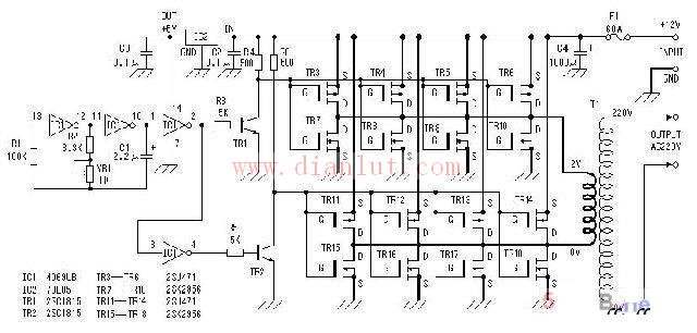
500W Inverter Circuit Diagram 1:
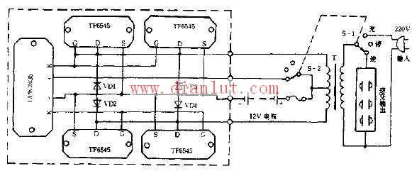
500W Inverter Circuit Diagram 2:
Car 12V Inverter Circuit Diagram:
These diagrams illustrate the internal structure of inverter circuits, including components like transistors, capacitors, resistors, and transformers. Understanding these designs can be helpful for engineers, hobbyists, or anyone interested in building or repairing power electronics systems. Whether you're working on a DIY project or studying electrical engineering, these diagrams provide valuable insights into how inverters function and are constructed.
Smart Multimeter ,Smart Digital Multimeter,Digital Smart Multimeter,Multimeter Smart
YINTE TOOLS (NINGBO) CO., LTD , https://www.yinte-tools.com