Lm339 pin function diagram and application circuit

The following is the circuit diagram of LM339 pin function diagram and application circuit.
Lm339 pin voltage
1st foot: 5.14V, 2nd: 0.26V, 3rd: 18.45V, 4th: 5.12V, 5th: 4.7V, 6th: 3.86V, 7th: 4.02V, 8th: 1.37V, 9th: 4.76V, 10th: 5.64V, 11th: 11.8V, 12th: 0V
Typical application circuit diagram for LM339.
"lm339 application circuit"
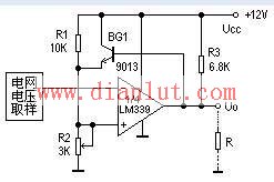
The image above shows an application of LM339 in a microwave oven to detect whether the grid voltage is normal. If it's not, the system stops immediately.
"lm339 voltage comparator circuit diagram"
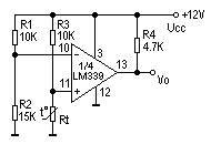
This figure demonstrates a typical LM339 voltage comparator application used for temperature detection. By adjusting R1, you can set the threshold voltage, effectively changing the temperature setting. The principle is straightforward—readers are encouraged to analyze it further.
The LM339 can also be used to form dual-threshold voltage comparators and various oscillator circuits.
Introduction to the four voltage comparator LM339 and nine typical application examples
The LM339 integrated block contains four independent voltage comparators. Key features include: 1) low offset voltage (typically 2mV), 2) wide supply voltage range (single supply 2–36V, dual supply ±1–±18V), 3) large internal resistance limit for comparison signals, 4) wide common-mode range (0–(Ucc–1.5V)), 5) large differential input voltage range (up to power supply voltage), and 6) flexible output potential selection.
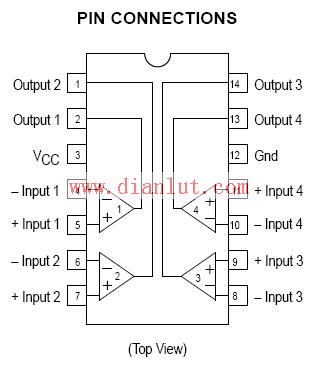
The LM339 is available in a C-14 package. Figure 1 shows its outline and pinout. Due to its versatility and wide applications, many IC manufacturers have developed similar four-comparator chips such as IR2339, ANI339, SF339, etc. These parts have similar parameters and can often be used interchangeably.
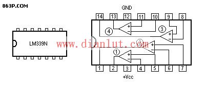
Figure 1
The LM339 is similar to an operational amplifier with a fixed gain. Each comparator has two inputs and one output. One input is called the non-inverting input (+), and the other is the inverting input (-). When comparing two voltages, a reference voltage (threshold level) is applied to one input, and the signal to be compared is applied to the other. If the + terminal is higher than the - terminal, the output turns off (open circuit). If the - terminal is higher, the output saturates (low potential). A difference of more than 10mV ensures reliable switching. This makes the LM339 ideal for weak signal detection. The output behaves like an open-collector transistor without a collector resistor, so a pull-up resistor (3–15kΩ) must be connected externally. Different resistor values affect the high-level output voltage. Additionally, multiple comparator outputs can be connected together for shared use.
LM339 battery automatic charger method
This charger using the LM339 voltage comparator is suitable for charging NiCd or NiMH batteries (sizes 5 or 7). It’s simple to build and includes automatic detection functionality. The working principle is as follows. As shown in the figure, the LM339 has four units, each for a rechargeable battery. Only one unit is illustrated here.
After the power supply is regulated by the three-terminal regulator IC1 KA78M05R, +5V powers the IC2 pin 3. This voltage is divided by resistors R1, R2, and R3 to set the inverting input (pin 4) at 1.42V as a reference. The non-inverting input (pin 5) is controlled by the battery voltage. When the battery is fully discharged, its voltage is below 1.42V, causing the output on pin 2 to go low. V1 becomes forward-biased, allowing +5V through V1’s collector-emitter and R5 (current-limiting resistor) to charge the battery. With R5 = 10Ω, the charging current is about 150mA. When the battery is full, its voltage reaches or exceeds 1.42V, triggering the comparator to flip. Pin 2 goes high, V1 turns off, LED2 (green) turns off, and charging stops automatically.
LED1 (red) indicates power (always on), while LED2 (green) indicates charging. In reality, when the battery is full, LED2 blinks. Once the battery voltage reaches 1.42V, the comparator flips, stopping the charge. However, if the voltage drops slightly, the comparator reactivates, restarting the charge. This creates a "floating charge" state, causing LED2 to blink.
LM339 to make a single limit comparator circuit
Figure 1a shows a basic single-limit comparator. The input signal Uin is applied to the non-inverting input, and a reference voltage Ur is connected to the inverting input. When Uin > Ur, the output is high (UOH). Figure 1b shows the transfer characteristics.
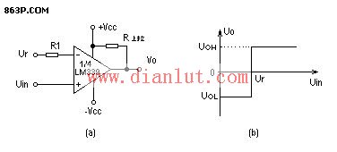
Figure 3 shows an overheat detection protection circuit. It operates from a single supply with a fixed reference voltage on the inverting input of 1/4 LM339. UR = R2/(R1+R2) * UCC. The non-inverting input voltage equals the thermal element Rt's voltage drop. When the temperature is below the set point, the "+" terminal voltage is higher, so the output is high. When the temperature rises above the set point, the "-" terminal voltage becomes higher, and the comparator flips, making the output zero. Adjusting R1 changes the threshold voltage for temperature control.
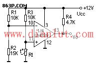
Image 3
LM339 makes hysteresis comparator
A hysteresis comparator is essentially a single-limit comparator with positive feedback. In a standard single-limit comparator, small interference near the threshold can cause output jitter. Adding positive feedback eliminates this issue.
Figure 1a shows a hysteresis comparator (Schmitt trigger). Figure 1b displays its transfer characteristics.
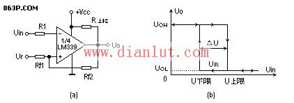
Figure 1
It's clear that when the output state changes, any interference within ΔU will not affect the stability of the output. However, this reduces resolution since the comparator cannot distinguish between two input voltages less than ΔU apart. The hysteresis comparator speeds up the response and prevents self-oscillation due to parasitic coupling.
To fix a trip point to a specific reference voltage, a nonlinear component like a diode can be added to the positive feedback circuit. Using the unidirectional conductivity of the diode allows achieving the desired threshold. Figure 2 illustrates this.
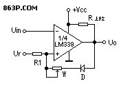
Figure 2
Figure 3 shows a part of the grid overvoltage detection circuit in an induction cooker. When the grid voltage is normal, U4 < 2.8V, and U5 = 2.8V. The output is open, and the emitter follower BG1 is on. When the grid voltage exceeds 242V, U4 > 2.8V, the comparator flips, and the output is 0V. BG1 turns off, and U5 is determined by R1 and R2, resulting in 2.7V. This ensures a stable state after flipping, preventing instability caused by small fluctuations in grid voltage. After overvoltage protection, the grid voltage must drop to 237V before the induction cooker resumes operation, which is the desired behavior.
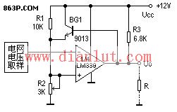
Image 3
LM339 produces dual limit comparator (window comparator)
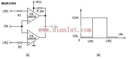
Figure 1 shows a window comparator made from two LM339s. When the input voltage Uin is between UR1 and UR2, the output is high (UOH). Otherwise, it's low (UOL). The window voltage ΔU = UR2 – UR1. This circuit is used to check if the input voltage falls within a specified range.
Using LM339 to form an oscillator
Figure 1 shows an audio square wave oscillator using 1/4 LM339. Changing C1 adjusts the frequency. For example, with C1 = 0.1μF, f = 53Hz; C1 = 0.01μF, f = 530Hz; C1 = 0.001μF, f = 5300Hz.
The LM339 can also be used to create high-voltage digital logic gates and interface directly with TTL and CMOS circuits.
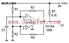
Figure 1
(Editor: Circuit Diagram)
Electronic Cigarette E-liquid,Electronic Cigarette E Juice,Fashion Electronic Cigarette ,Disposable Cigarettes Atomizer
Longhua Manxueling Trading Company , https://www.mxlvape.com