Busway installation method - Solutions - Huaqiang Electronic Network
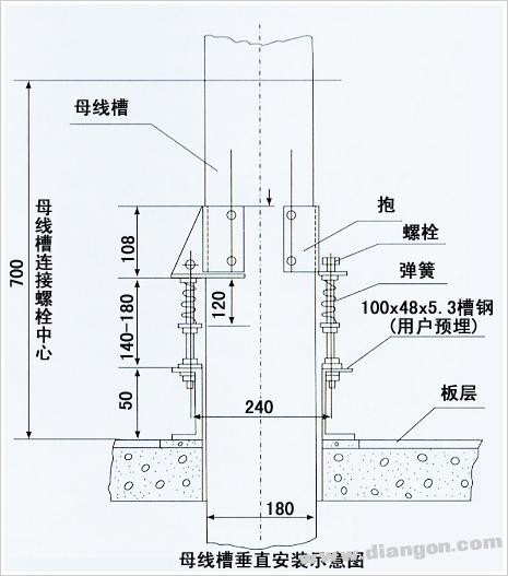
1. The busway channel should be installed horizontally with a spacing between brackets of 500 to 2500 mm. For vertical installation, the spacing should be between 600 and 3600 mm.
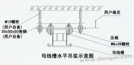
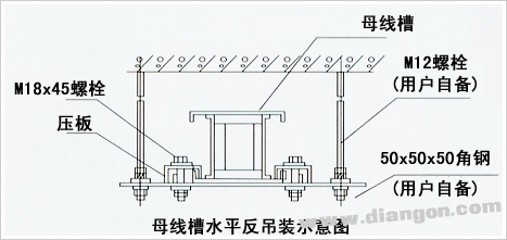
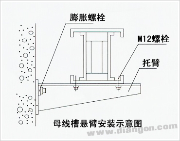
2. When installing vertically, the mounting bracket must be drilled into the side plate of the channel and fastened using M6-M8 bolts.
3. During installation, it is recommended to follow the construction plan from the feeding system to the branch line for optimal performance.
4. The basic sequence for closed busway installation includes: selecting the wiring direction, fixing the brackets, securing the slots with four bolts, adding busbar joint plates and insulating pads between phases, inserting a single-head bolt through the insulating sleeve, pre-drilling holes in the busbar, tightening both ends, attaching the upper and lower covers, and finally securing the channel to the bracket.
5. The beginning, middle, terminal, and housing of the channel bus must be reliably connected to the grounding grid of electrical equipment. Insulating channel housings should be connected using flat copper strips or yellow-green phase cables between the grounding bolts of adjacent channels to ensure a complete grounding system.
6. After installation, perform an insulation resistance test using a shaking table before power transmission. For low-voltage busways, the insulation resistance should not be less than 20 MΩ. For 6–10 kV high-voltage busways, it should not be less than 1200 MΩ, and for 35 kV busways, it should not be less than 3000 MΩ.
7. Before power transmission, the 6–35 kV bus channel must undergo a 50 Hz power frequency withstand voltage test and a DC leakage test. It can only be put into operation after passing these tests.
8. Three months after commissioning, check and tighten the busbar joint bolts to ensure good contact at the joints.
9. At least once a year, inspect the following items for the bus route:
(1) Tighten all fixing bolts, especially those at the busbar joints, and check for signs of burning due to poor contact or overcurrent.
(2) Test the insulation level using a shaking table and check for aging of insulating materials.
(3) Inspect the connection between the busway and the grounding grid.
(4) Ensure that the inside and outside of the busway are free from dust and condensation.
10. Notes:
(1) Before any maintenance, turn off the power supply and hang a "Man-operated, strictly closed" warning card.
(2) Before starting maintenance, ensure the system is discharged and use a grounding rod to short-circuit and ground the phases safely.
11. Storage of the busway:
Store the busway in a dry and well-ventilated indoor area to prevent moisture, rain, snow, dust, or foreign objects from entering the passage.
ZOOKE provides you with safe and reliable connector products, with 1.0 spacing products providing more possibilities for limited space and creating more value for the research and development and production of terminal products.
1.00 wire to board connectors,1.0 connectors,ZOOKE connectors
Zooke Connectors Co., Ltd. , https://www.zooke.com