Design and research of automotive fault diagnosis expert system software
At present, China's car holdings are increasing rapidly, and there are more and more imported cars, and the models are complex and diverse. As a result, many maintenance units cannot repair or meet the needs of maintenance due to lack of technical guidance from maintenance experts. In order to improve the utilization rate of vehicles and reduce economic losses, the development of automotive fault diagnosis expert system and the use of advanced equipment such as computers for fault diagnosis are the needs and inevitable trends of the development of the situation.
The vehicle fault diagnosis expert system is a computer intelligent software program that can simulate the diagnosis idea of ​​the maintenance expert for fault diagnosis. To develop such a system, it is first necessary to summarize and refine a large number of actual maintenance experience of experts in the field of vehicle maintenance, and compile it into a knowledge base to form the core part of the expert system. Secondly, an inference engine needs to be established, and the inference engine can be based on the fault signs provided by the user or Abnormal phenomena, using the knowledge in the knowledge base, reasoning according to certain reasoning strategies, and then obtaining the diagnosis results. The structure of the expert system is shown in Figure 1. 
This article refers to the address: http://
1 Overall design and construction of a practical vehicle fault diagnosis expert system, not only has a friendly human-machine interface, efficient reasoning strategy, convenient knowledge acquisition means, but also a complete database and image library, as well as a powerful help system. The overall structure block diagram is shown in Figure 2. The fault diagnosis module adopts different diagnosis methods according to different types of deterministic faults and non-deterministic faults. For deterministic faults, a diagnostic tree method is mainly used to describe the diagnosis process, and all possible possibilities are listed from the fault phenomenon. The fault parts that produce such phenomena are eliminated one by one according to the most convenient judgment method, and the exact fault location is finally determined. For non-deterministic faults, such as abnormal noise of the engine, the logical relationship between the fault phenomenon and the cause is not obvious. Or unclear situation, using fuzzy diagnosis method, through fuzzy statistics to simulate the reasoning method of maintenance experts in discriminating abnormal sound parts, so as to find out the cause of the fault, so as to start and repair, without manual Diagnostics saves time and improves the efficiency of vehicle maintenance. The database provides a large amount of data about the car, including general data of the car, usage data, maintenance adjustment data of the engine and the chassis, etc., so that the maintenance workers can check in time while working, without having to take time to access the book materials. The image library provides users with a large number of beautiful car images with an introduction to various models. 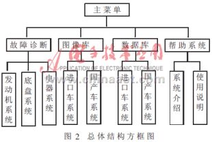
2 Design of each functional module
2.1 Design of fault diagnosis module This module searches the fault clues mastered by the user in the way of human-machine dialogue, and imitates the diagnosis ideas of the maintenance experts to reason, and then finds the fault components and causes step by step. The diagnostic flow diagram is shown in Figure 3. . According to the specific conditions of the car, the diagnostic module is divided into three parts, and the detailed structural block diagram is shown in Figure 4. 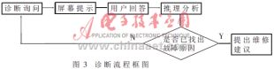
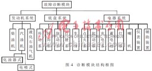
Taking the engine system as an example, when establishing the diagnostic sub-module of the diesel engine, a more vivid tree-like graphical diagnosis scheme is adopted for its fault characteristics. When making a diagnosis, the system determines the next displayed branch based on the user's response to the inquiry until the diagnosis proceeds to the leaves (to find out the cause of the failure). At this time, it is determined that the button becomes available from the failure (the failure state is not diagnosed), and the preview and the print screen are popped up after being pressed, and the human-machine interface is shown in FIG. 5. 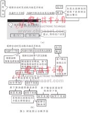
2.1.1 Difficulties in Diagnostic Software Design To implement this fault tree diagnosis method, first draw all the tree diagrams on the form. When initializing, first set the visibility of all objects in the full screen VISIBLE=.F., then according to each Buttons, query the logical relationship between files, and write the actions to be performed when the button is pressed (CLICK property). For example: when a button is pressed, the program is executed:
Thisform.line25.visible=.t.
Thisform label11.visible=.t.
2.1.1.1 Design of the wrong selection function Sometimes, when the user presses a button, after the corresponding diagnosis content has been displayed, it is found that the selection is wrong, and the repentance is returned to press the upper or upper level. a button. The system must allow this error to occur and fulfill its requirements by adding some statements to the CLICK attribute of each button so that the properties of the other objects are changed back to VISIBLE= except for the content VISIBLE (visible) that should be displayed. F. (invisible), this requires controlling each object item by item. For example, after the button on the right has been pressed and the content of the next level is popped up, the user repents and presses another button on the left side, and the system resets the content popped on the right side to VISIBLE=.F., hides it, and The content on the left is popped up (see Figure 6). 
When the user's diagnosis is completed, browsing and printing functions are allowed. First, to determine whether the user has completed the diagnosis, that is, whether the final result of a certain branch has been displayed. If not, browsing is not allowed. Then, with the content corresponding to each step as a record, all the records in the diagnosis process of this branch are added to the USER. Fault field, and the functions such as browsing can be realized. After writing the additions for each branch, you completed the design of a form.
2.1.1.2 Design of the diagnostic recording process The difficulty of this part is to add the design of the diagnostic process record. Originally designed to include a statement in each selection button, the diagnostic process for that part was added to the table as a record, but later considering that the user might repent, how to identify the added error record and delete it, It is a big problem. After repeated research and experimentation, it was decided to adopt the existing method, that is, ignore the user's diagnosis steps, and only the diagnostic branch that was finalized. First determine which branch is based on the final result, and then add the content of the branch in the OK button.
2.2 Design of Database Module The automotive database module mainly consists of five parts: database, work interface, information retrieval, printout, and system guidance information processing. The database part is the data source of the entire system and is one of the most important components of the system. According to the extremely large and complex nature of automotive data. The structure of the whole system adopts the database mode of “tree branch, module association, and segment constructionâ€, and its structure is shown in Figure 7. 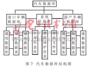
Corresponding to the database module, the working interface also adopts an interactive association call method. Each work interface corresponds to a corresponding database and can be called from each other. Due to the use of structured programming, each work interface appears as a sub-function, which increases the flexibility of the system and makes the whole system more hierarchical. The entire working interface network is shown in Figure 8. The working environment of the whole system is an interconnected network structure. In this working interface network, the user can simply jump in each part of the data without having to care about the database. At the same time, each data interface is closely connected with the search interface and the print interface, and the data acquisition is more convenient and quick. 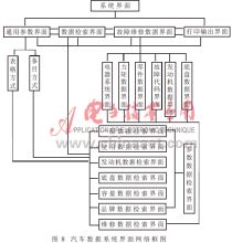
The data retrieval module is a central part of the entire system. Because measuring the success of a database system depends largely on the speed and completeness of its search function. According to the characteristics of large data record entries, large number of data fields and large amount of bytes occupied by the car, the automobile database system adopts a new way of view retrieval. The retrieval condition is obtained through the working interface, passed to the view as a parameter, retrieved by the view, and then the temporary data table of the retrieval result is generated by the view. The temporary data table is mapped to the search interface to realize the display of the search result. This method uses a structured query (SQL) view retrieval. The transmission and discriminating of the retrieval conditions is relatively simple, and the query speed can be satisfactory when using the RUSH MORE technology. At the same time, the use of the generation of temporary tables can greatly reduce the CPU and memory usage and speed up system performance. In the actual test, the system retrieved 298 records that met the complex conditional relationship in 8 databases (more than 50,000 data), which took only 0.27 seconds and the query results were satisfactory. Moreover, the temporary table of the view is also utilized in the system to send the update property, and the search result editing function is added. The user can first retrieve the required data records by using the search interface, and use the function to modify the data and send it to the original data table to better realize data management.
Semiconductor Ceramic Component,Power Surge Protector Zinc Metal Oxide Varistor,Zinc Oxide Varistor
Film Capacitor,Ceramic Capacitor Co., Ltd. , http://www.nbxinqing.com