Turn computer sound card into oscilloscope with software and simple circuit
For example, have you used Arduino to control the servo, and you need precise pulse width modulation to decide whether to rotate clockwise or counterclockwise? With an oscilloscope, when you write a program, you can know how much the current pulse width and the required pulse width are still different. When processing analog signals, you can also detect the difference between the current frequency and the target frequency, or measure what frequency needs to be filtered. There are a large number of digital electronic devices, and the time difference of the signals becomes extremely important, so an oscilloscope is required for time detection.
Basically, an oscilloscope is a data capture device that records the voltage on a circuit. There is another device on the computer that also has this function, that is, the sound card, the main difference is the voltage that both can handle and the frequency of the measured voltage (discussed in detail later). Because the sound card on the computer can only handle lower voltages (about /-.6V to .8V), turn the voltage down. The key to successfully making an oscilloscope probe is to accommodate a higher voltage input and turn the voltage down so that the sound card can handle it.
The following steps will teach you how to make this probe. The finished product here is suitable for the line input of the sound card, and the line can usually receive stereo input, so this probe will have two channels. If you want to use the microphone input on your system, you only need to make a probe with only one channel, because the microphone input is usually mono. Once you're done, take a look at the differences between this set of oscilloscope and lab-level models and discuss their limitations.
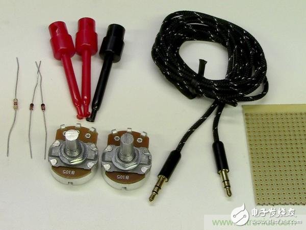
material
1M ohm linear potentiometer (2), RadioShack website item #271-211: Please be sure to buy a linear type instead of an audio type.
4.7k ohm resistor, 1/4 or 1/2 watt (2), RadioShack website article number #271-312
1N4148 general diode, non-Ziner type (4), RadioShack website article number #276-1620: This diode can withstand the frequency we need to deal with, and the current carried by the circuit also has about .6v positive Provides adequate protection to voltage and microphone and line inputs.
6' 1/8" (3.5mm) stereo audio cable, RadioShack website item #42-2387: If the microphone input is only connected by a single channel, a mono line can be used.
Mini Test Clip Adapter, RadioShack Website Item #270-372
Hexagon Control Knob, RadioShack Website Item #274-415
Hole plate: Buy a double-sided type, or create a double-sided hole plate with two general hole plates (see step 2)
Electronic wire, not necessary: ​​used to make double-sided hole plates (see step 2).
tool
Make: it luxury tool set, RadioShack website item #64-246.
Mini Hot Melt Glue Gun, RadioShack Website Item #55066341
Bow saw
Welding helper
Step first step: circuit diagram overview
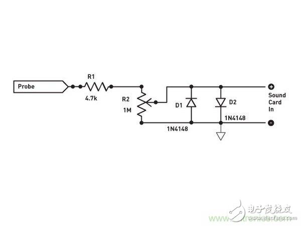
The circuit diagram of the oscilloscope is simple. Connect the probe to the circuit where it needs to be measured. The signal comes in from the probe and is directly connected to the 4.7k ohm resistor (R1).
From there, the signal is passed through a 1M ohm potentiometer (R2) to adjust the voltage to the sound card.
Note: The value of the resistor and potentiometer is between ±10V. You can use a voltage of up to 30V without any problem of excessive current.
The adjacent configuration of the two diodes (D1 and D2) protects the line input of the sound card and opens when the input signal exceeds 7V. The 4.7k ohm resistor (R1) also limits the current through the diode, thereby protecting the diode.
Note: If you need to measure a higher voltage, it is recommended to use a second voltage divider on the supply of the circuit. In addition to these components, stereo audio lines, clip wires, and hole plates for mounting all components are required.
Note: This project is designed according to the double-sided hole plate (that is, the copper pad on both sides). If you don't have one, don't worry, teach you how to do it yourself in the next step!
Step 2: Make a double-sided hole plate
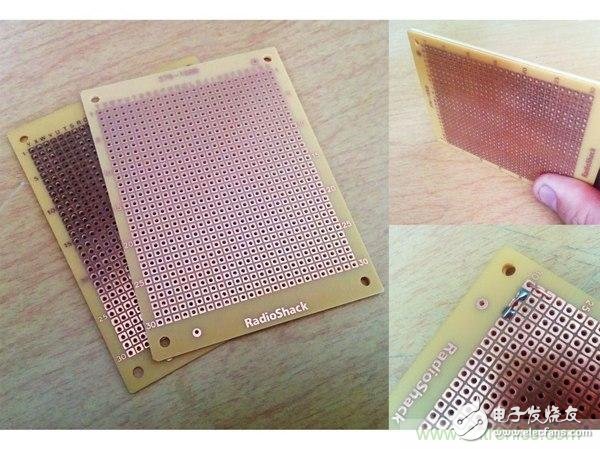
If you don't have a double-sided copper pad, you can do it yourself. Take two identical hole plates, placed back to back, with the copper pads facing outward.
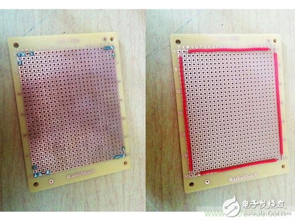
You can glue the hole plates together (if glue is used, it is recommended to use glue), or use the characteristics of the hole plates, that is, they are welded and fixed.
Cut a 22AWG solid wire of appropriate length to form a "frame" on the four sides of the hole plate (Figure 2). Then let the wire cross over one side and solder it to the back to form a solid double-sided hole plate with copper pads on both sides.
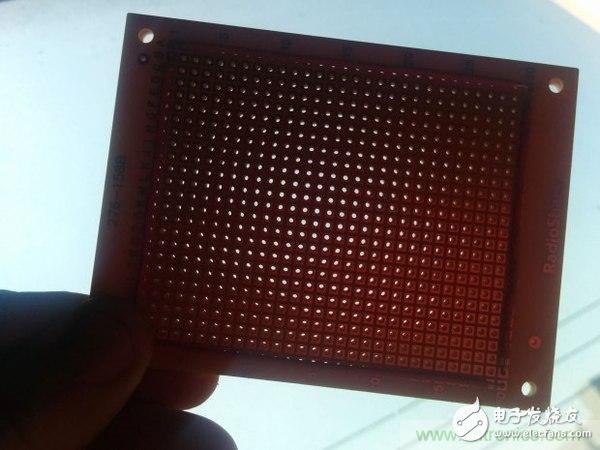
The holes on all the holes are now fully aligned (Figure 3). Although a border is made, this size hole plate has 644 holes available.
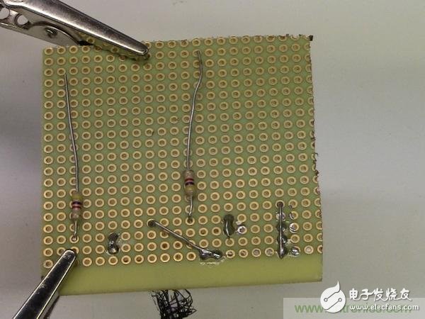
The third step: component configuration
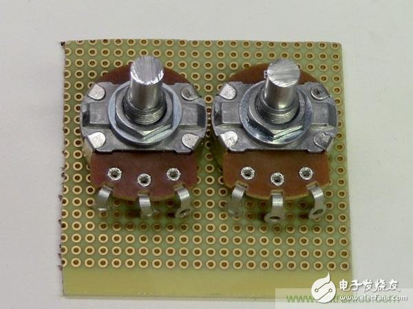
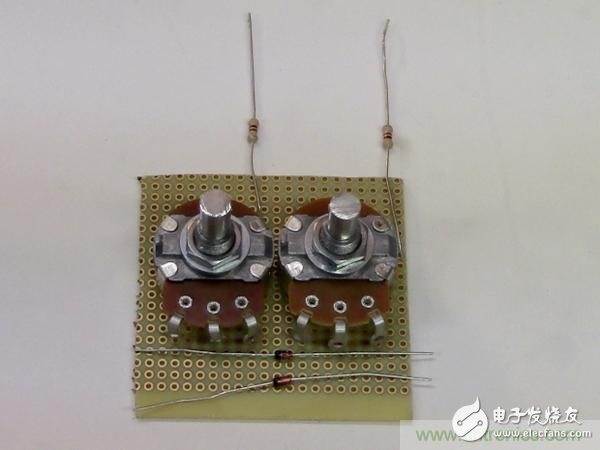
First place the largest component: the potentiometer on the board to determine the required size. Then cut the hole board to the appropriate size, arrange the other main components, and look at the general configuration.
After configuring 2 potentiometers and 4.7k ohm resistors, find the best place for the diode. Mark the position of the potentiometer electrode on the board as a reference later.
Step 4: Connect the audio cable
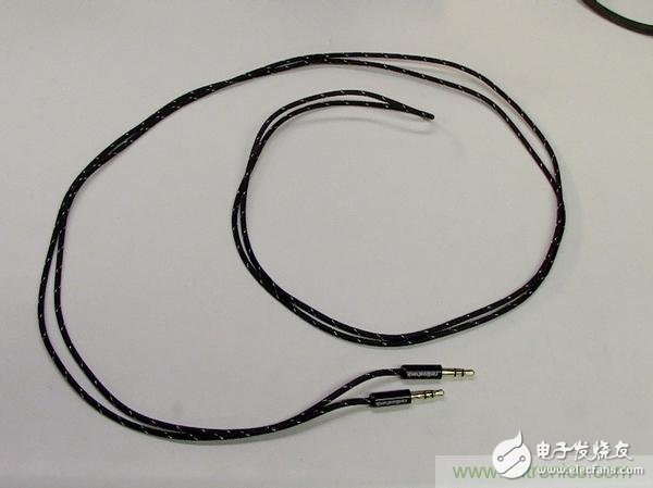
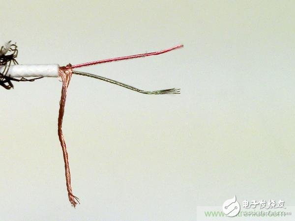
Cut the audio cable to the length required for the desk or notebook configuration. Then strip the 3 different wires in the cable. One of the uninsulated winding wires is the grounding wire, and the other two insulated wires will be used as the input channels 1 and 2. Special effort is required when stripping channel line insulation because they are very small.
Note: There is a small trick to burn the insulation to the required length with a soldering iron and simultaneously apply tin to the electrode. Don't forget to wipe the soldering iron afterwards.
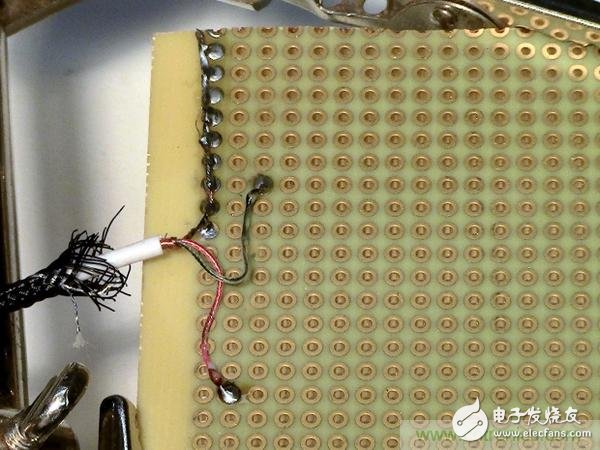
Next, connect the line to the hole plate according to the reference point of the potentiometer. The channel line will be connected to the center electrode of the potentiometer. The ground wire can be pulled aside and fixed in multiple locations because there will be many contacts that need to be grounded.
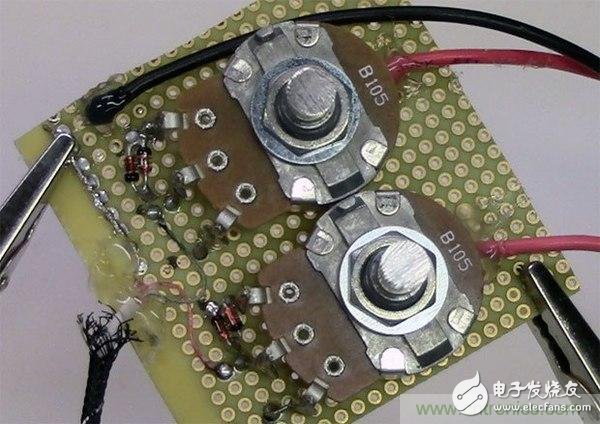
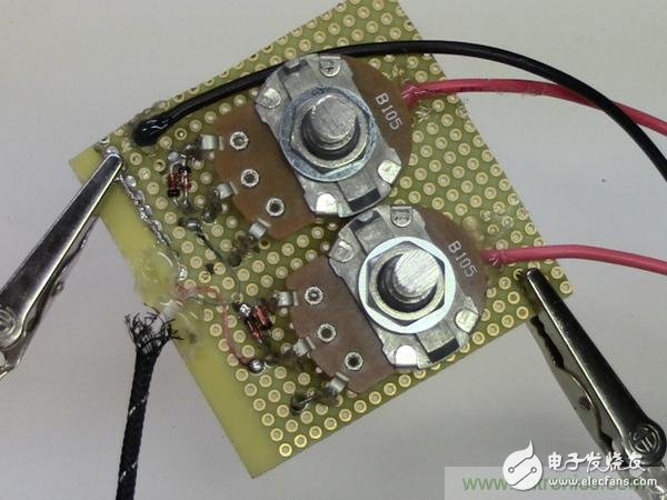
Step 5: Fix the components on the board
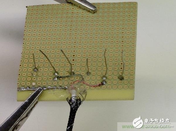
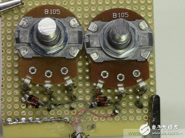
Each potentiometer has 3 contacts. In the photo, from left to right are grounded, connected to the sound card, and connected to the 4.7k ohm resistor. Hot melt adhesive is used when fixing the potentiometer to the board.
Finally, connect 2 diodes to each channel between the ground and the sound card. Remember that one of the diodes is connected to ground from the negative pole and the other is connected to ground from the positive pole.
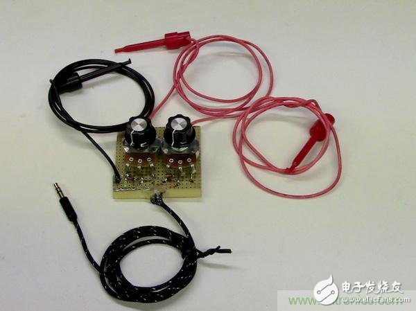
Step 6: Complete the clamping

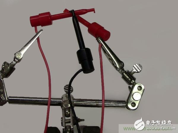
After connecting the cable, connect the other end of the cable to the appropriate position on the hole plate. The red line is the signal line and is connected to a 4.7k ohm resistor (opposite the potentiometer contact). The black wire is connected to the ground rail of the hole plate.
The hole plate and cable solder joints require some kind of pull release so that they are not accidentally pulled out. Hot melt adhesives are very useful, and it is good to drop hot melt adhesive on 3 joints.
The electronics and hardware have been partially completed, and the potentiometer can be fitted with a housing and knob.
Step 7: Install the software
Note: Unfortunately, the sound card oscilloscope software is only available in Windows. I still can't find the Mac version after trying hard. (Maybe I will write one myself and then release it!)
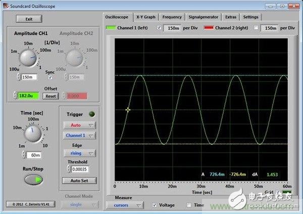
Step 8: Software Usage – 60Hz Comparison
The software is surprisingly powerful, not only with dual channel support (if available on your hardware), but also with FFT measurements, cursors, XY plots and signal generators!
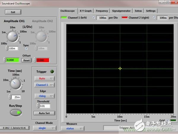
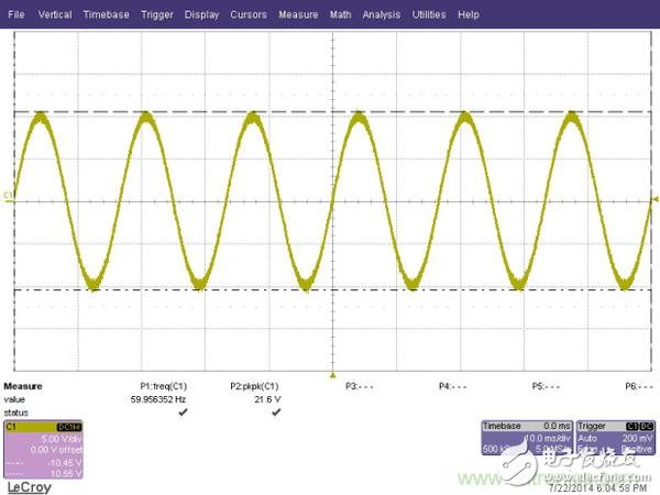
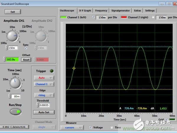
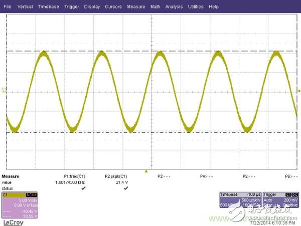
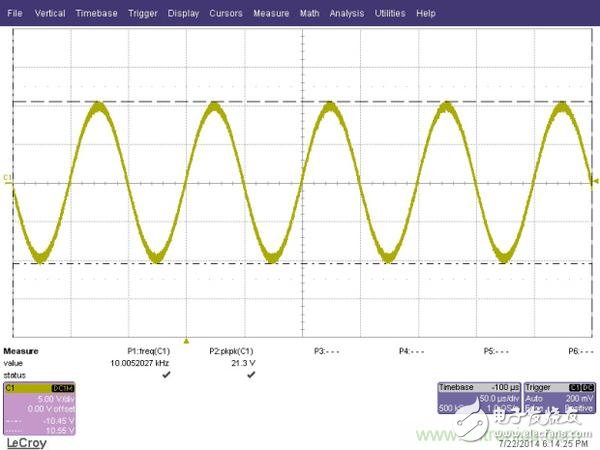
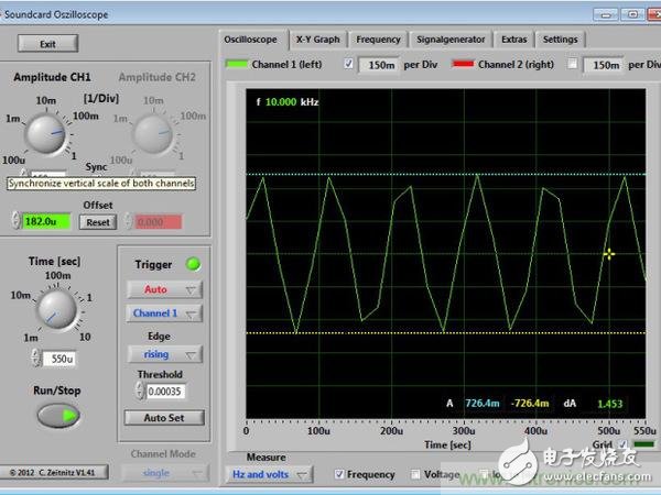
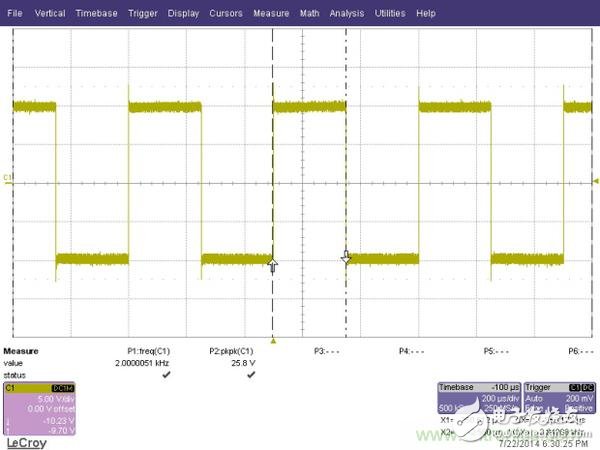
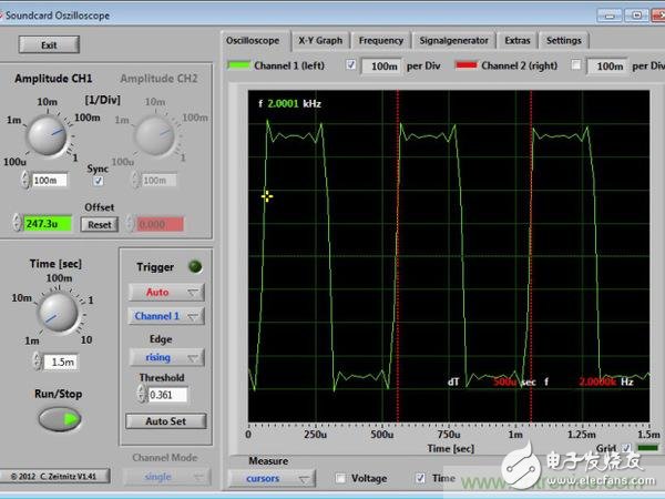
Note: The first image shows the factory-made desktop oscilloscope output, while the second and third maps are the output of the sound card oscilloscope.
Both desktop and sound card oscilloscopes can easily handle 60Hz sine waves. You can select the CURSOR to measure time and voltage data. However, the voltage is not corrected by the resistor divider, so the exact voltage on the circuit cannot be displayed. The software has optional calibration points available.
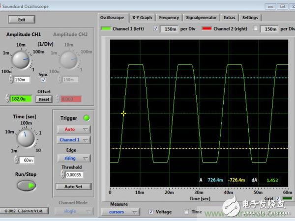
Take a closer look at the third picture, you can see that the wave front of the sine wave is somewhat flattened. This is because the potentiometer is too strong, so that the diode begins to conduct electricity. This situation is often referred to as "wave clipping." If you find a waveform cut, simply turn the potentiometer back until the waveform is corrected, that is, the wave front of the sine wave is not flattened.
Step 9: Software Usage – 1kHz Comparison
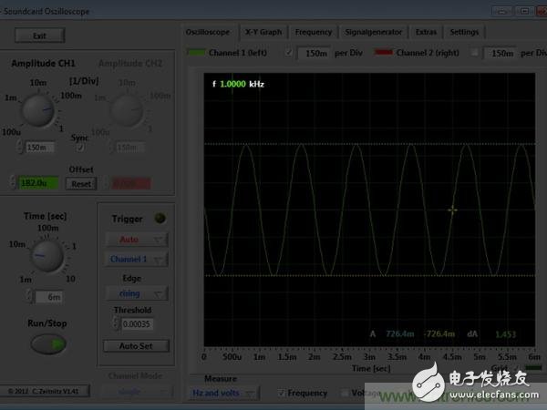

Note: The sound card oscilloscope will even display the measured frequency for easy confirmation.
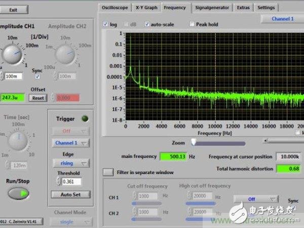
Step 10: Software Usage – 10kHz Comparison
The oscilloscope is limited by two main conditions:
Bandwidth, which is the range of frequencies that can be effectively measured. A laboratory-grade oscilloscope has a bandwidth of 200 MHz here, which means that it can be effectively measured in the range of 0 to 200 MHz. The bandwidth of the sound card is much smaller, about 20–15 kHz. Outside of this range, the measurement results are not accurate.
Sampling frequency The sampling rate of the laboratory-grade oscilloscope here is 2GS/s! The sound card in the computer is only about 44kS/s. This is why faster waveforms may not be accurately measured. Basically, the sampling frequency is the frequency at which the system measures the voltage. The laboratory-level sampling frequency can reach 2 billion times per second, while the sound card type is only 44,000 times. You might think that this DIY tool would have no effect, but it is not! For many players' circuits, the speed of 14kS/s is used to measure the pulse width and frequency. When the circuit is getting faster, consider buying a lab-grade model.
The eleventh step: software - square wave and FFT
Wireless Retro Speaker,Waterproof Retro Speaker,Portable Vintage Speaker,Rechargeable Vintage Speaker
Shenzhen Focras Technology Co.,Ltd , https://www.focras.com