500w inverter circuit diagram
Here is the circuit diagram for a 500W inverter. This type of inverter is commonly used to convert DC power from a battery into AC power for household appliances or electronic devices.
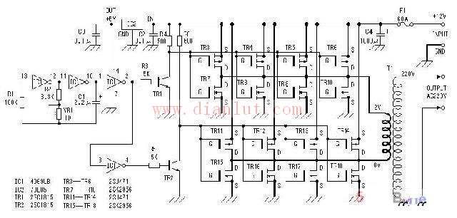
500W Inverter Circuit Diagram 1:
500W Inverter Circuit Diagram 2:
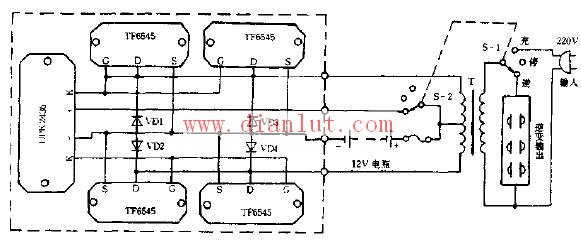
Car 12V Inverter Circuit Diagram:
These diagrams can be useful for engineers, hobbyists, and DIY enthusiasts who are working on power conversion projects. Whether you're building a portable power system or trying to understand how inverters work, these visual guides offer a clear representation of the internal components and connections involved in a 500W inverter setup.
Digital Display Test Pen ,Power Tester Pen,Voltage Pen,Digital Voltage Tester
YINTE TOOLS (NINGBO) CO., LTD , https://www.yinte-tools.com