do you know? The accuracy and resolution of VR or AR can be further improved!
Eye contact: eye sclera coil tracking virtual reality
Joint compilation: Zhang Min, Chen Jun
Summary
Eye tracking technology is becoming more and more important in the mobile and wearable systems field, especially for emerging virtual and augmented reality applications (VR and AR). Current human eye tracking methods for wearable AR and VR headsets rely on optical tracking and achieve typical accuracy (0.5 degrees to 1 degree). We have studied a high temporal and spatial resolution eye tracking system based on magnetic radiation tracking using scleral search coils. This technology used to rely on a large generator coil a few meters in diameter, or it needed to restrain the user's head. We present a wearable sclera search coil tracking system that allows the user to move around and eliminate the head restraint/room-sized coil. Our technology involves a uniquely positioned generator coil and a new calibration method that produces a non-uniform magnetic field through a smaller coil. Using this technique, we can estimate the direction of the eye with an accuracy of an average of 0.094 degrees.
ACM classification keywords
H.5.m information interface and presentations (such as HCI), etc.
Author Keywords
Eye Tracking; Magnetic Tracking; Sclera Search Coils; Head Mounted Displays; Virtual Reality
Introduction
Accurate and high-speed human eye tracking is crucial in ensuring critical scenes in virtual reality (VR) and augmented reality (AR). Human eye tracking can ensure a new kind of gaze mediated input and techniques such as foveal rendering, which can reduce the amount of AR/VR calculation required by focusing the quality of the user's gaze, wearing a helmet The traditional motion capture system cannot be used on the monitor (HMD). High-precision human eye tracking also ensures that the human visual vestibule system responds to virtual reality.
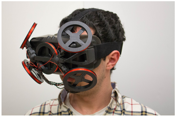
figure 1. Human-eye scleral coil tracker can be clipped to HMD without the need for head-mounted or room-sized magnetic field coils
Research on existing wearable human eye tracking systems has focused on using and improving optimal tracking techniques. However, the highest standard for high-resolution human eye tracking is still magnetic radiation tracking with a scleral search coil (SSC). Scleral coil tracking can record small amplitude motions with high time (greater than 1 KHz) and spatial resolution (calibration error less than 0.1). In this technique, the head is placed between large Helmholtz coils that produce a uniform magnetic field. The traveler is embedded in the silicone ring (placed in the sclera of the eye). The magnetic field induces a voltage in the scleral coil depending on its direction. The system estimates the direction of the eye by examining the amount of voltage induced by the wire drawn by the coil.
The biggest limitation of SSC tracking is that it requires a large generator coil with a few meters in diameter, or requires head restraints such as a bite bar or a chinrest. To overcome this limitation, we have proposed a wearable sclera search coil tracking system compatible with HMD, such as those used in virtual reality systems. By mounting the smaller generator coil directly in the HMD, as shown in Figure 1, we constrain the position of the coil relative to the head to allow the object to move freely and eliminate the need for a head-fixed/room-sized coil.
Inserting the sclera search coil is an inherently invasive procedure that is usually performed by local anesthesia and requires a trained technician to supervise it. Therefore we do not recommend that consumers use scleral coil trackers in VR/AR systems. We only hope that researchers use it in wearable HMD scenarios that require high precision, high temporal resolution tracking, and spatial resolution. For example, physics researchers can use our system to obtain high-resolution data to study the twitch (0.2 degree) motion that occurs during the eyes while presenting visual targets on the HMD to better understand the changes in eye behavior. . Existing vision-based HMDs human eye trackers often do not have sufficient accuracy and time resolution to learn in these areas. We also want to encourage researchers to consider using the SSC system to obtain ground truth data for the evaluation of more traditional optical human eye tracking systems. Another possible application of our system is in the medical field where scleral coil tracing is the gold standard for subtle vestibular diagnosis, ophthalmology and neurological diseases.
The specific contribution of this article is as follows:
1. Movable, head-mounted system for high-speed and high-precision human eye tracking (no external instruments are required).
2. The unique coil placement position ensures reconstructed gaze and scleral coil position in space.
3. Calibration techniques for different fields created by smaller generator coils.
4. High-precision machine testing with five degrees of freedom, which allows us to thoroughly describe the magnetic field and ensure the accuracy of the evaluation as well as an accurate SSC tracking system that is independent of the user's fixed accuracy.
Background and related work
In this section, we discuss the working principle and research of magnetic field human eye tracker and SSC system. At the same time we also talked about the alternative method (video, electrogram) of the magnetic field human eye tracker.
Eye tracking system
Video-based tracking is the most commonly used method for human eye tracking. High-end commercial video human eye tracking systems such as the SR Research EyeLink 1000 Plus can be simplified at 1000 Hz with a precision of 0.33 degrees. Tobii and SMI's commercial wearable human eye tracking system uses infrared light-weight eyeglasses. These systems typically have 0.5 degree accuracy and output data from 60Hz to 100Hz, but it is not designed to be compatible with HMD. Dual Purkinje Tracking is an alternative high-precision time tracking technology, but it requires complex mirror sets and servo motors, which makes head-mounted display implementations more difficult. To learn more about video-based wearable trackers, see Bulling and his colleagues' comments.
Video-based human eye tracking methods have recently been used for HMD. For example, the SMI tracking system can be used as an additional software package for Oculus Rift DK2 and Samsung Gear VR. Accuracy of 0.5 degrees to 1 degree is achieved at a data rate of 60 Hz. Additional solutions by Arrington Research and Tobii demonstrated the same performance. Although the solution will improve over time, the current solution data rate and accuracy is very low, and is designed for a specific HMD visual design.
Another more ancient method for human eye tracking is eye electrocardiography (EOG). The eye is a source of electric dipoles between the cornea and the retina; this corneal retinal potential can be as high as 1 mV when recording EOG and can be a function of eye orientation. Electro-oculography measures the movement of the eye by measuring the electrodes placed around the eye in the corneal retinal potential. The EOG signal is noisy and is usually used only for horizontal eye movements or to detect blink and eyeball postures.
Scleral coil tracking
Scleral coil tracking is the gold standard for human eye tracking, especially in the medical research community. Robinson developed this technique in 1963. Collewijin and his colleagues refined the technique in 1975 and provided a data rate of up to 10KHz with a calibration accuracy better than 0.1 degrees. The subject wore a coil with a silicone ring embedded in the sclera (Figure 2). A thin line connects to the external measuring unit. The external generator coil generates a magnetic field that includes the voltage generated in the coil (which is amplified and measured).
Scleral coil tracker works
Scleral coil tracking relies on alternating magnetic fields presented in front of the user's eyes. Using an alternating current to drive an electromagnet (formed by a coil) is a very effective method for generating a magnetic field that oscillates at a specific frequency. According to the Biot-savart law, a current flowing along the coil of the wire generates a magnetic field, similar to Figure 3.
According to Faraday's Law of Induction: The oscillating magnetic field produced by the contact of these generator coils with the sclera induces the same frequency current in the scleral coils. The current in the scleral coil is directly proportional to the rate of change of magnetic flux through the coil's surrounding surface.
The magnetic flux passing through the coil depends on the orientation of the coil in the magnetic field. If the coil is perpendicular to the magnetic field (that is, the normal vector of the coil is perpendicular to the field), the magnitude of the magnetic flux and the induced voltage will be the greatest. When the coil and the magnetic field are parallel, the induced voltage drops to zero. If the coil is turned over, the voltage will have a phase shift of 180, which can be expressed as a negative amplitude.
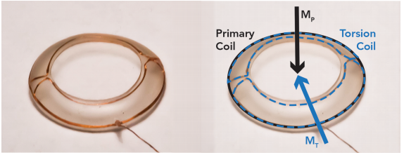
figure 2. Kronos' 3D twisted scleral coil. The original coil captures the flowing magnetic flux by contact, while the torsion coil captures the flux across the contact.
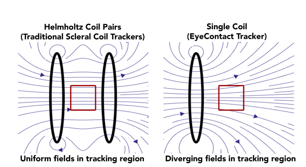
image 3. (Left) The conventional scleral coil tracker utilizes a Helmholtz coil pair to generate a magnetic field that produces a very small amount, where the magnetic field is insensitive to small head movements. (Right) A field produced by a single coil in our system, which produces a diverging magnetic field.
Using this phenomenon, the SSC tracker can evaluate the orientation of the human eye by measuring the magnitude of the voltage signal in the scleral coil. However, because a single magnetic field information is not sufficient to fully specify gaze, most sclera use three orthogonal coils to track the generator coil (operating at different frequencies or orthogonal). By testing the scleral coil signals at different frequencies, we can test the flux of each generator coil. In general, magnetic fields are generated by large coil pairs called Helmholtz coils. As shown in Figure 3 (left), these coil pairs simplify stare assessment by creating a uniform magnetic field in the x, y, and z direction regions. In this area, the direction and amplitude of the magnetic field are relatively insensitive to the position of the scleral coil, which allows the user to perform a small amount of movement. With a smaller Helmholtz coil system (less than 1 meter in diameter), the uniform volume is only a few centimeters wide, and the limitation is to keep the head in this roll. These design constraints require a large amount of space and cost constraints, which prevents the technology from being applied beyond the medical facility center. Nowadays, researchers use scleral coil human eye tracking for the diagnosis and biomedical research of vestibular nervous system diseases.
Some SSC systems also seek to reverse the visual axis of the eye. In a conventional coil system, the single coil within the scleral contact is not sufficient to determine the twist of the eye. Therefore, some scleral contacts contain a second twisted coil. As shown in Figure 2, this coil forms two cycles around the eye (on two different levels). Although the main coil captures the magnetic flux through contact, all the current in the torsion coil is due to the magnetic flux passing through the coil. The concept naturally takes into account the twisted coil as a second coil (perpendicular to the primary coil).
Scleral coil tracking improvements
In order to increase the usability of the SSC method, several projects have attempted to eliminate measurement devices that connect wires to the scleral coils. Reulen and Bakker introduced a dual magnetic induction (DMI) technique using a short-circulating scleral coil. As before, when the user is placed in an alternating magnetic field generated by a set of coils of Helmholtz, current is generated in the scleral coil. The electric current in the circle produces a second magnetic field that can be detected directly by a set of coils in front of the eye. Bremen and his colleagues conducted a similar experiment - the wearable version of DMI technology. Fundamentally, because it is necessary to measure the secondary magnetic field, DMI has a weaker signal than noise. Further, they still require large external coils to generate the magnetic field. In our EyeContact system, we use a standard wired SSC and focus on improving the design of the generator coil. Therefore, the accuracy of our system and some of the standard SSC trackers do not require external instruments and can be connected to an HMD.
Roberts and his colleagues demonstrated a wireless scleral coil system (on a similar principle). Using a series of capacitor rings embedded in silicon to shorten the scleral coil, they created a resonant circuit. The resonant circuit generates an oscillating current in the coil and is maintained by a nearby transmitter coil. Multiple receiver coils measure the attenuation signal. The relative strength of the signal in the receiving coil determines the direction in which the eye gazes. Although an HMD adaptation can be used, the performance specifications of this technology have not been verified.
Thomassen and his colleagues noted that many trackers have small, non-uniform magnetic fields that make head-unconstrained experiments difficult. When the head moved out of the uneven area, the author changed the tracking algorithm of the ready-made scleral coil tracking system in order to correct its performance. However, this technology still requires a large number of external instruments. Plotkin and his colleagues also tried to solve the problem of non-uniformity by using a planar transmitter placed at a fixed location. Although their design is more portable, it is too large to be installed on the user, and in the experiment it does not allow the user to move more than 10 centimeters. On the contrary, our system allows users to move freely and is limited only by the HMD's tether, scleral coil and excitation coil.
system design
We demonstrated EyeContant, designed a scleral coil tracking system for virtual reality headsets. We used five small-scale coils as shown in Figure 4 (left), and then strictly installed the coil on the user's head, and constrained the direction of the flux to the user's head. Each coil oscillates at a unique frequency and creates a unique magnetic field. A key challenge in our system is that, contrary to Helmholtz coils, these coils produce a divergent field, and the direction of the magnetic field varies greatly with position, as shown in Figure 3 (right). Further complicating our system is that the scleral coils shift in space along the surface of the eye when the eye rotates. As it moves relative to the magnetic field coil, both the size and direction of the scleral coil field change. However, gaze estimation is still possible because the dissolving five magnetic fields are unique in each space. Because the field is different for different eye positions, we can also recover the positional offset between the tracker and the scleral coil. This allows us to consider all changes or slips in the user's face HMD.
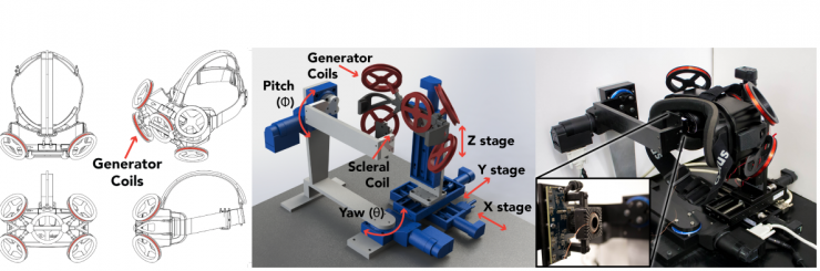
Figure 4. (Left) The scleral coil tracker consists of five field coils mounted around the HMD. Its purpose is to capture the Oculus Rift DK2, but it can be easily adapted to other HMDs. (Center, right) The 5-DOF mechanical assessment device allows us to control the scleral coil positioning (pitch, yaw) and adjust the position of the HMD/tracker relative to the scleral coil. (right, inset) The scleral coil is placed on the arm of the test device.
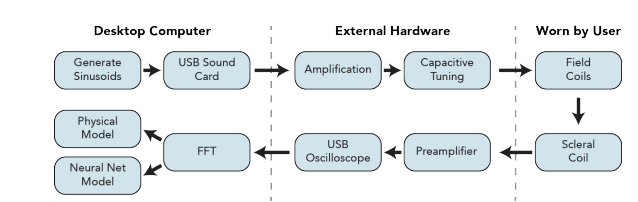
Figure 5 Scleral coil tracking signal pipeline. The sine signal is synthesized from a desktop computer and amplified before passing through the generator coil. This induces a voltage in the scleral coil (which is amplified and processed on a desktop computer).
The five generator coils used in this arrangement ensure that each eye has three coils and can provide a reliable signal (the central generator coil is shared by both eyes). Although these three generator coils are sufficient for reconstructing the position of the eye, the two coils farthest from each eye provide a weak signal that can further improve the accuracy of gaze estimation. The coil size is optimized to balance the magnetic field strength and the weight of the tracking device. By placing the coil close to the eye, we can produce the same magnetic field as a conventional magnetic field coil while using a smaller current (less than 1A per roll).
For scleral coils, we used Chronos Vision's three-dimensional scleral contact (which contains a twisted coil). Contrary to previous efforts, we used twisted coils that are not only torsional. Instead, we used the entire scleral coil as a biaxial magnetic field sensor to measure the three components of the two magnetic fields.
Each generator's coil is wound around a circular 3D printed ABS frame (8 cm in diameter) with a 50åŒ26 AWG magnet. The coils are mounted together and form an HMD attachment. Our design is adapted to Oculus Rift DK2, but it can be easily modified to adapt to other VR devices. The system diagram is shown in Figure 5. The coil is driven by a sinusoidal current synthesized by a desktop computer. Commercial audio hardware can be used for synthesis and amplification by maintaining a frequency range that can be stimulated by the coils in the audio. We used a desktop computer running Max7 software to synthesize a sine wave with a sampling rate of 192 kHz and sine waves at frequencies around 15 kHz, 16 kHz, 17.1 kHz, 18.3 kHz, and 19.6 kHz. The frequency is selected in conjunction with the position of the Fast Fourier Transform (FFT) box and the intervals are not equal to avoid intermodulation components. Use an 8-channel USB audio interface to convert the synthesized audio signal to an analog voltage signal. The five voltage signals of the audio interface are amplified by an independent Class D amplifier to increase the power through the field coil.
Since the excitation coil presents an inductive load to the system, a capacitive tuning adapter is used to remove the imaginary component of the impedance. The adjustment adapter includes five channels, each with a step-up transformer and a stack of shunt capacitors. By adjusting the capacitance of each channel while monitoring the voltage and current through the coil, it is possible to maximize power transfer to the coil.
Before measuring the signal of the scleral coil, we used an instrumentation amplifier (INA128) to magnify it. Then we use a 4-channel signal differential input USB oscilloscope (from Pico Technology) to sample the main and torsion signals.
Run MATLAB software on a desktop computer connected to a USB oscilloscope and recording data at a rate of 1 MSa/s. The software buffers the signal from each eye (from the main and twist coils) into a 16-millisecond buffer with 25% overlap. 4 -term The Blackman-Harris window applies to each buffer because their length is not an integral multiple of the number of frequency cycles of the field. This window function is selected because of its sidelobe attenuation. We can calculate the FFT for each window and select the 5 main components and 5 twist components that correspond to the frequency bin of interest. By using these narrow frequency bins, we also avoid the magnetic interference of all environments or electrons in the HMD; when the HMD is in use or an application is in use, the scleral coil measurements have not changed. For each frequency component, we save the amplitude and the complex FFT phase. Continuous measurements can be averaged to further increase the signal-to-noise ratio.
When choosing the frequency corresponding to the FFT samples, we also forced each window to contain an integer period of a specific frequency, keeping the FFT phase between each window. However, due to the small time difference in the components of the system, in practice, the phase drifts significantly with time. Considering this drift, we used a 10-second calibration cycle to measure and track the phase drift rate. (Min) During this period we will measure and track the phase change rate. Occasionally, we will rearrange additional changes that slowly accumulate. With this technique, the adjusted shift only occurs in 180 increments when the magnetic flux through the coil reverses due to focus change. We can reconstruct the signed value by comparing the adjusted phase with the phase of known focus.
Machine test device
To evaluate the performance of the scleral coil tracker, we established a 5-DOF machine test setup that can adjust the coil orientation as well as the HMD position. As for the coil, see Figure 4 (center, right). The scleral coil is mounted on a U-shaped shield inside the plastic bracket. Automatic rotation from the Physik Instrument can swing the arm around (θ). This allows us to adjust the yaw and pull up the coil direction. The HMD and generator coils are mounted in three linear stage systems (x,y,z). This allows us to move the HMD in space according to the resolution of the collar 0.5um, simulating different mounting methods for the HMD such as front or back. Because we are using a spherical pattern of the human eye, the scleral contact placed on the surface of the eye moves in the space where the eye rotates, depending on the radius of the eye. For a system with a non-uniform magnetic field, this is an important point, because the magnetic field environment will change with the focus of attention, although the HMD is fixed on the user's head. Without explaining this, the scleral contact will be mounted on the center of rotation of Re = 8.5mm to simulate human eye behavior. To calculate the offset of the scleral coil, we consider the position of the HMD (x, y, z) and the center of attention of the eye, as in Equation 1.

These five automated steps can all be controlled on the desktop. To enable automatic scanning of the entire field of view, we integrated the controlled phase into MATLAB data collection software. When the area is measured, we scan the coil in the ideal range of yaw (θ) and pitch (φ), and also scan the HMD position in space (x, y, z). The MATLAB recording software automatically records the value of the scleral coil in one second after the cessation of a phased movement to prevent the influence of the test device offset.
The data is collected from 30 ゚ to 30 3 in increments of 3 ゚ along the horizontal (θ) and vertical (φ) axes. This is where you can compare with other eye trackers. We scan HMD simulation slides with a scan range of 7.5mm to 7.5mm along the x-axis (edge ​​to edge) on a 3mm increment, or 5mm increments along the y-axis (front to back) from 5mm to 0mm , - or 5mm to 5mm along the z-axis (from top to bottom) at 2mm increments, as shown in Figure 4 (middle). This also represents scanning 441 points based on 6×2×6=72 positions in 31,752 data point spaces. It takes 8 hours to collect this data.
Gaze estimation model
We compared the two modes of gaze assessment. First we use physical methods to model the tracker around the magnetic field. By comparing scleral coil measurements, we expect to measure within a given magnetic field and measure the position and orientation of the scleral coil. We compare this method with a neural network model that can directly evaluate the direction within a given coil test.
Use physical mode for gaze assessment
The physical model evaluates the five magnetic field ranges throughout the world of the eye, and then uses scleral coil measurements to reassess these vectors in the coil space. The direction of the eye is determined by the rotation, and rotation is the best explanation for the change in the mutual aid system. As summarized in FIG. 6, to assess the deficiencies of the tracker with respect to the eyes and the gaze direction of each frame, the pattern includes corrections for each previous use.
The five fields of magnetic field will be modeled according to a fixed position and direction. Based on the knowledge of the geometry known to the tracker and the current through each engine coil, we can calculate the expected field of the magnetic field, B(P), at any eye position based on the standard equation of the magnetic field of the coil on the axis of symmetry. With this information, as well as the position and orientation of the given scleral coil, we can predict what we expect to be able to predict from the scleral coil.
Proofreading program
When the user wears the HMD for the first time, there is an unpredictable offset between the tracker and the center of rotation of the eye, because the skeletal structure of each user and the placement of the HMD are different. Our proofreading program hopes to assess the HMD shift. In this procedure, we must understand the sensitivity of the primary and torsional coils and the radius of the eyeball, because these are the degrees of movement of the scleral coil when the eye rotates. We use a 36-point proofing program in which the user looks for a target at a specific location on the screen. We simulated this on a machine test setup by moving the steps to the required direction.
Given the proofreading point (known direction of gaze) and the magnetic field range model, we evaluated the sensitivity of the scleral coil using MATLAB's Global Optimization Toolbox, and the HMD offset (Xe, Ye, Ze) and the radius of the eyeball (Re) . The ability to evaluate the HMD offset was evaluated by using the test device to transfer the HMD and collapsing 72 different offsets within the sliding range. At each point, we used 36 points for each proofreading program. The average European-style error in evaluating the HMD offset is 0.72 mm.
This model rationally explains the test results observed in the scleral coil. However, there were some errors in the assessment (the average error in the primary coil was 1.5%). The cause of this result was not caused by special eye movements. The irregularities in the magnetic field were caused by the HMD shift in this area. One of the key points is that these errors are all relative. It is possible to model the residual error on each of the 10 scleral coils and these are predicted by the physical mode as a function of gaze position. This means that if we know the focus of the user's gaze, we can adjust the evaluation from the scleral coil so that the user best applies the physical mode. When modeling the residual error as a function of the gaze position, using 36 proofpoints is very likely to know the correct pattern. We used MATLAB to fit the 36 calibration points of the function while using bi-harmonic interpolation to evaluate every ten scleral coils. In your assessment, we rely on iterative promotion methods and use related models to improve gaze assessment.
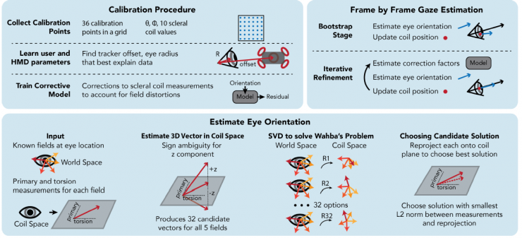
Figure 6: Summary of proofreading procedures and gaze evaluation functions. The 36-point procedure was started when the user brought the HMD for HMD excursions and evaluation of the eyeball radius. This was to train the sclera evaluation model. For each frame, the direction of the eye is iteratively evaluated and refined using the updated coil position and correction factor. The direction of the eyes was evaluated using the SVD solution to the Wahba problem.
Frame-by-frame gaze evaluation
When evaluating the direction of the eye, we first use the magnetic field model to calculate the five expected magnetic field directions at the scleral coil position, which can be calculated by the HMD offset in the proofreading. Initially, because we do not know the direction of the eye, we do not consider the range in which the coil moves with the eye; now we assume a fixed coil position. Next, we will reconstruct five evaluated magnetic field directions in the coil space of the scleral measurement. We consider that the scleral coil as a biaxial sensor will output a magnetic field range vector within its range, this vector is determined by the primary and torsional coil direction (see Figure 6, bottom). To reconstruct the third component, we normalize the measurement by increasing the magnetic field strength and the associated primary and torsional coil sensitivities, so the scleral sensor effectively reports the two components of a unit vector. We can rebuild the third component as:
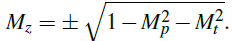
However, considering that the third area component has a significant symbol ambiguity. We think that there are two possibilities for these five magnetic field fields, so for each magnetic field evaluation, there will be 32 candidate sets.
For each candidate set, we have five known magnetic field vectors (physical modes) and five magnetic field evaluations of the coils in the unknown reference frame (from the scleral coil and the third evaluation component). This is an example of a problem with Wahba. In this example, an attempt was made to find a rotation matrix at the home of two cooperative systems in a given series of weighted observations. We evaluated gaze using a solution for solving the Wabha problem. The weight of each field is based on the average signal-to-noise ratio previously calculated for each coil.
This process outputs 32 candidate solutions, all of which determine the direction of the eye. To select between solutions, we calculate the expected value of each candidate sclera coil test and select the closest solution to the test results.
This initial assessment does not take into account the correct mode or eye movements that occur with rotation. Since the initial gaze estimate is often around 3 å离 from the average, we can calculate an estimate of the eye position and the necessary corrective factors. In order to make the gaze assessment more accurate, we will update the magnetic field at the new eye position and adjust the scleral coil evaluation result according to the correct mode to recalculate the gaze direction. The next gaze assessment will be more accurate, allowing us to better assess the correct conditions and scleral coil position. We will repeat this process until the gaze of the assessment is coincident; it usually takes 5 iterations. Applying this program to the 405 test direction includes a 72 HMD offset, and we achieved an evaluation error of about 0.18 。. The small part of the model performance of these points is shown in Figure 7 (top right). Figure 8 is a summary of the cumulative distribution function (CDF).
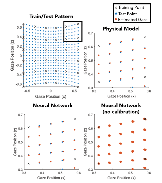
Figure 7: Condensation view shows training (black X), test (blue circle), and evaluation (orange circle) gaze position, with y=1 in the plane. (Top left) 36 points for training, and the remaining 405 points for testing. (lower right) Gaze assessment of physical and neural network models and a small portion of real test results. (bottom right) shows the position of all 72HMD's gaze shifts for the proofreading neural network mode.
Neural network model
As an alternative to the physical model, we trained the neural network system to understand the effects of magnetic field offset and distortion caused by HMD and eye movement. To train this mode, the user must perform a 36-point proofreading program. Each data point includes 10 scleral coil assessments. Forty neurons are used in the hidden layer and the output layer is composed of two neurons that are trained to output the direction of the scleral coil.
In physical mode, we use the test device to evaluate the accuracy of the gaze evaluation model. For every 72 HMD offsets within the drop limit, we use 36 training points to train the separated neural networks and use the remaining 405 points for testing. This method achieves a 0.094 ã‚š average error at the HDM offset and test point. A gaze assessment for an HMD shift is shown in Figure 7 (bottom left). The complete results are summarized in Figure 8 as CDF.
Free proofreading mode
To reduce the sensitivity to slip, we tried to explore whether neural networks can be trained in independent locations. In this method, the two-step pattern is used to evaluate the coil position and direction search results. Training these models requires a lot of training data, and it also makes the proofreading process difficult to implement. In addition, it is not possible to determine the position of the search coil within the space worn by the user. Therefore, we introduced a free-calibration tracking technique using pre-training patterns.
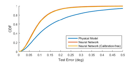
Figure 8: Accuracy of all positions in the CDF gaze direction of the physical mode, neural network mode, and free proof mode. The physical model achieves an average error of 0.18 。. The other two neural network models performed better than the physical model, with an average error of 0.094 ゚ and 0.099 ゚ respectively.
First there are 10 input node neural networks (5 primary observations and 5 twist observations, respectively), and 40 hidden nodes and 3 output nodes (x,y,z) all use 72 HMD offsets collected at 32. The proofreading point in the position is trained. The average Euclidean error in the remaining 27,880 points is 0.084 mm.
We will now strengthen the original gaze mode through location assessment. Enter 13 nodes, 10 are scleral coils, and 3 are x, y, and z positions that are evaluated in space. Again, we performed proofreading training based on the training positions collected and tested at the remaining points. The average error in the test is around 0.099 。. This result is also summarized in the target map of FIG. 7 (bottom right) and in the CDF in FIG. 8 .
discuss
Based on the physical model and neural network model, we presented two methods of gaze assessment. The average gaze direction error for the physical mode is 0.18 ã‚š. By modeling the magnetic field, the model allows us to understand the magnetic field environment of the scleral coil and it can be better developed by itself. For example, future work may focus on online proofreading programs, reverse assessments, or proofreading using information from both eyes. These applications become more difficult in opaque neural networks.
With an average error of 0.094 ã‚š, the neural network model can better approximate the magnetic field environment of the tracker and the distortion caused by the HMD. The free proofreading neural network can improve usability by evaluating the HMD slip and positioning of the eye at each frame. However, since this mode is based on training from data collected from the test device, it is not particularly clear how to extend it to users in different magnetic field environments. At present, we are studying the manifestation of this technology under the conditions of human participation.
The focus of future exploration will be the combination of these models. By providing a neural network from a physical model to evaluate the magnetic field, we can simplify the training and shorten the training time.
In the proofreading-based model, we expect that when the user first wears the HMD or whenever the HMD shifts on the face, they perform a 36-point proofreading process. We have implemented a mobile algorithm that can automatically remind the user to make adjustments when needed.
Our system samples the scleral coil at 1 Msa/s. After buffering and browsing, the gaze evaluation criteria will be output at a rate of 244 Hz. By reducing the window size and increasing the overlap width, the output data rate can be significantly increased. We intend to implement a native code algorithm or use dedicated editable logic hardware. Similarly, we can increase the time resolution by using high-frequency sinusoidal signals or by using extra widths. We also explored the average sample time, as it is common in many SSC tracking systems. Although we can increase the accuracy of the neural network to 0.03 ã‚š, we choose to maintain a higher data rate.
In the evaluation, we are more concerned with machine testing as a human agent. This allows us to collect more comprehensive datasets with respect to position and orientation, and gives us reliable real-world references. These references can be independent tracker accuracy and independent fixed accuracy for human users.在设计测试装置时,我们考虑了许多让眼ç›åœ¨HMDä¸è¿½è¸ªå˜å¾—困难的ç事。例如,我们考虑到了巩膜线圈ä½ç½®ä»Žæµ‹è¯•è£…ç½®ä¸å¿ƒä½ç½®çš„å移导致了巩膜线圈的空间移动。我们åŒæ ·ä¹Ÿè€ƒè™‘到了在3轴翻译阶段系统ä¸å®‰è£…HMD和追踪器导致的HMDæ»‘ç§»ã€‚å› ä¸ºå¯¹äºŽè®¸å¤šçš„VR应用æ¥è¯´ï¼Œæµ‹é‡å‡è§†çš„ä½ç½®å·²ç»è¶³å¤Ÿäº†ï¼Œæ‰€ä»¥æˆ‘们并未优先考虑评估眼ç æ‰è½¬ï¼Œå¹¶ä¸”这一评估能æ供一个完整的å‡è§†è¯„估。虽然我们物ç†æ¨¡å¼å¯¹äºŽæ‰è½¬æä¾›äº†ä¸€ä¸ªè¯„ä¼°ï¼Œä½†æˆ‘ä»¬å¹¶æœªå¯¹å…¶å‡†ç¡®æ€§è¿›è¡Œè¯„ä¼°ï¼Œå› ä¸ºæµ‹è¯•è£…ç½®åªè®©æˆ‘们在æ‰è½¬å¢žåº¦åœ¨10゜以内进行调整。未æ¥çš„测试装置会包括精准的æ‰è½¬æŽ§åˆ¶â€”—4゜至4゜的范围内,这将对我们的模å¼æä¾›æ›´åŠ ç²¾å‡†çš„æ‰è½¬è¯„ä»·ã€‚ç„¶è€Œä»¥æ ¡å¯¹ä¸ºåŸºç¡€çš„æ¨¡å¼å¹¶æœªè€ƒè™‘对称æ‰è½¬ï¼Œä½†æ¤ç±»æƒ…况在å´ç»å¸¸ä½œä¸ºå‡è§†åŠŸèƒ½çš„一部分出现。
in conclusion
眼神交æµæ˜¯ä¸ºè™šæ‹Ÿå’Œå¢žå¼ºçŽ°å®žHMD设计的一个巩膜线圈追踪系统,HMD能实现高速和高准确度的移动眼ç›è¿½è¸ªè£…置,并且是在没有仪器帮助的æ¡ä»¶ä¸‹å®žçŽ°çš„ã€‚æˆ‘ä»¬çš„æœºå™¨æµ‹è¯•è£…ç½®è®©æ ¡å¯¹å’Œè¯„ä¼°éƒ½çœŸå®žå¯è¡Œã€‚我们æè¿°äº†ä¸€ä¸ªæ ¡å¯¹ç¨‹åºå’Œä¸¤ä¸ªä¸åŒçš„方法对å‡è§†è¿›è¡Œè¯„估:物ç†æ¨¡å¼å¹³å‡è¯¯å·®ä¸º0.18゜,神ç»ç½‘络模å¼å¹³å‡è¯¯å·®ä¸º0.094゜。我们希望这一系统对于需è¦åœ¨HMDä¸çš„高质é‡è¿½è¸ªå™¨ç ”究者æ¥è¯´ï¼Œä¼šæ˜¯ä¸€ä¸ªæœ‰ç”¨çš„工具。
Via: the original site of the paper
哈尔滨工业大å¦æŽè¡æ°å‰¯æ•™æŽˆçš„点评: 人眼追踪技术在移动和å¯ç©¿æˆ´å¼ç³»ç»Ÿé¢†åŸŸæœ‰ç€é‡è¦çš„作用,特别是新兴的虚拟和增强现实应用(VRå’ŒAR)方é¢ã€‚ç›®å‰ï¼Œå¯¹äºŽå¯ç©¿æˆ´çš„ARå’ŒVR头戴产å“,人眼追踪方法主è¦ä¾èµ–于光å¦è·Ÿè¸ªï¼Œè¿½è¸ªä¼°è®¡ç²¾åº¦å¤šåœ¨0.5度至1度之间,而本文给出了一ç§å¯ç©¿æˆ´å¼çš„巩膜æœç´¢çº¿åœˆï¼ˆSSC)跟踪系统,它å…许用户å¯ä»¥èµ°åŠ¨ï¼Œå¹¶ä¸”ä¸éœ€è¦å¤´éƒ¨çš„约æŸå’Œå¤§çº¿åœˆã€‚该技术涉åŠåˆ°ä¸€ä¸ªç‹¬ç‰¹å®‰ç½®çš„å‘ç”µæœºçº¿åœˆå’Œä¸€ä¸ªæ–°çš„æ ¡å‡†æ–¹æ³•ï¼Œå®ƒå¯ä»¥é€šè¿‡æ›´å°çš„线圈产生ä¸å‡åŒ€ç£åœºã€‚使用该项技术æ¥ä¼°è®¡çœ¼ç›çš„æ–¹å‘,å¯ä»¥å¾—到平å‡æ ¡å‡†ç²¾åº¦ä¸º0.094度的估计精度,从而å¯åº”用于高精度和高时空分辨率追踪的å¯ç©¿æˆ´å¤´ç›”显示(HMD)场景,其缺点是巩膜æœç´¢çº¿åœˆæ’入需è¦å±€éƒ¨éº»é†‰ï¼Œè¿™ä¸æ˜¯ä¸€èˆ¬äººèƒ½æŽ¥å—的。
PS : This article was compiled by Lei Feng Network (search “Lei Feng Network†public number) and it was compiled without permission.