Return loss measurement of T3 / E3 / STS-1 LIU
Abstract: This application note discusses how to measure and improve return loss (RL) in a line interface unit (LIU) —DS3150 from Dallas Semiconductor—applications. The definition, requirements, measurement and improvement methods of return loss are discussed.
Return loss defines that when a high-speed signal reaches the terminal of a transmission line, if the transmission line is not well terminated, part of the signal energy will be reflected toward the transmitter. This reflected signal is mixed with the original signal, which will cause the original signal to be distorted, making it difficult for the LIU receiver to correctly recover the clock and data.
Return loss is the power ratio of the original signal to the reflected signal (expressed in dB). Therefore, the return loss indicates the relative size of the reflected signal, and also reflects the degree of matching or mismatch of the transmission line terminal. If the measured return loss of the LIU card is 20dB at a given frequency, it means that the reflected signal at this frequency is 20dB less than the original signal power. Return loss requirements For E3, ITU G.703 and ETS 300-686, the specified input return loss is listed in Table 1, and the output return loss is listed in Table 2.
Table 1. Minimum return loss at the input
Table 2. Minimum return loss at the output
Dallas Semiconductor's LIU Return Loss Measurement ETS 300-686 specification A.2.5 and A.2.6 rules describe the test equipment and procedures for measuring E3 return loss. The test device shown in Figure 1 is used to measure the input return loss and verify whether it meets the requirements listed in Table 1. The output return loss measurement device is similar, except that the measurement device is connected to the transmitter output rather than the receiver input.
Figure 1. Return loss measurement device
In the device of Fig. 1, the return loss bridge uses A57TLSTD of Wide Band Engineering, Inc. Two 50Ω / 75Ω impedance converters (A65L from Wide Band Engineering) are used to connect the 75Ω bridge to the 50Ω signal generator and 50Ω spectrum analyzer port. The 75Ω precision resistor on the right side of the bridge in Figure 1 is part of the return loss bridge. Advantest's R3132 spectrum analyzer serves as a signal generator and spectrum analyzer.
In the device of Figure 1, the generator provides a sinusoidal signal with a peak value of 1V in the frequency range of 860kHz to 51550kHz.
To check the test setup before measuring the return loss, the bridge's NTP interface (the interface on the left in Figure 1) should be connected to a test load of 75Ω ± 0.25%. In the device of Figure 1, this precision resistor is a component in the return loss bridge of Wide Band Engineering Company. When using this resistor as the test load, the return loss should be more than 20dB higher than the return loss required by Table 1. Figure 2 shows the return loss measured using the device of Figure 1 under a 75Ω ± 0.25% test load. At a frequency of 1720 kHz, the return loss measured by the device is 45.27 dB.
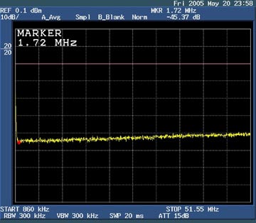
Figure 2. Return loss of 75Ω test load
Connect the NTP interface of the bridge to the receiving port of the DS3150DK evaluation board, and use a 330Ω standard termination resistor. The return loss measured at 1720kHz is 15.27dB, as shown in Figure 3. This value does not meet the requirements in Table 1. The following will explain how to improve the return loss to meet those requirements.
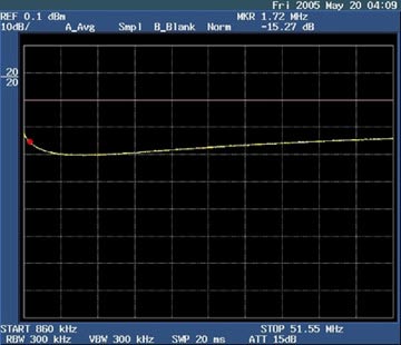
Figure 3. DS3150DK's return loss improvement The DS3150 application circuit's return loss has several methods to improve the DS3150 LIU's return loss: The termination resistance value was changed from 330Ω to 390Ω. Replace the PE-65968 transformer with a T3002 transformer, and add a 100nH series inductance to the primary winding. Improve the return loss of the DS3150 by changing the termination resistance (from 330Ω to 390Ω). The standard termination network of the DS3150 receiver is shown in Figure 4. Because strictly following the correct characteristic impedance is very difficult for PCB wiring, it is usually necessary to adjust the ideal 330Ω termination resistance value to improve return loss.
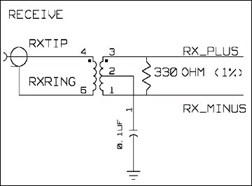
Figure 4. The original terminal network of the DS3150DK
When using the DS3150DK circuit board, replacing the 330Ω termination resistor with a 390W resistor can greatly improve the return loss. With a 390Ω termination resistor, the DS3150DK has a return loss of 18.01dB at 1720kHz (Figure 5), and a return loss of 23.39dB at 34.01MHz (Figure 6). Both of the above values ​​can meet the requirements in Table 1.
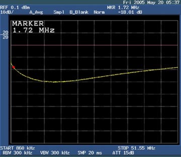
Figure 5. After the DS3150DK terminal network is adjusted, the return loss at 1720kHz
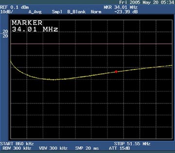
Figure 6. After the DS3150DK terminal network is adjusted, the return loss at the frequency of 34.01MHz is improved by changing the transformer and adding a 100nH primary winding series inductance. The following adjustments have been made: Replace the PE-65968 transformer with a T3002 transformer; connect a 100nH inductor in series with the primary winding.
After adjustment, the DS3150 receiver using a standard terminal network is shown in Figure 7.
Figure 7. The adjusted DS3150DK terminal network
Figure 8. DS3150DK return loss at 1720kHz after adjusting the terminal network
Figure 9. DS3150DK return loss at 34.37MHz after adjusting the terminal network
Return loss defines that when a high-speed signal reaches the terminal of a transmission line, if the transmission line is not well terminated, part of the signal energy will be reflected toward the transmitter. This reflected signal is mixed with the original signal, which will cause the original signal to be distorted, making it difficult for the LIU receiver to correctly recover the clock and data.
Return loss is the power ratio of the original signal to the reflected signal (expressed in dB). Therefore, the return loss indicates the relative size of the reflected signal, and also reflects the degree of matching or mismatch of the transmission line terminal. If the measured return loss of the LIU card is 20dB at a given frequency, it means that the reflected signal at this frequency is 20dB less than the original signal power. Return loss requirements For E3, ITU G.703 and ETS 300-686, the specified input return loss is listed in Table 1, and the output return loss is listed in Table 2.
Table 1. Minimum return loss at the input
| Frequency Range | Return Loss |
| 860kHz to 1720kHz | 12dB |
| 1720kHz to 34368kHz | 18dB |
| 34368kHz to 51550kHz | 14dB |
Table 2. Minimum return loss at the output
| Frequency Range | Return Loss |
| 860kHz to 1720kHz | 6dB |
| 1720kHz to 51550kHz | 8dB |
Dallas Semiconductor's LIU Return Loss Measurement ETS 300-686 specification A.2.5 and A.2.6 rules describe the test equipment and procedures for measuring E3 return loss. The test device shown in Figure 1 is used to measure the input return loss and verify whether it meets the requirements listed in Table 1. The output return loss measurement device is similar, except that the measurement device is connected to the transmitter output rather than the receiver input.
Figure 1. Return loss measurement device
In the device of Fig. 1, the return loss bridge uses A57TLSTD of Wide Band Engineering, Inc. Two 50Ω / 75Ω impedance converters (A65L from Wide Band Engineering) are used to connect the 75Ω bridge to the 50Ω signal generator and 50Ω spectrum analyzer port. The 75Ω precision resistor on the right side of the bridge in Figure 1 is part of the return loss bridge. Advantest's R3132 spectrum analyzer serves as a signal generator and spectrum analyzer.
In the device of Figure 1, the generator provides a sinusoidal signal with a peak value of 1V in the frequency range of 860kHz to 51550kHz.
To check the test setup before measuring the return loss, the bridge's NTP interface (the interface on the left in Figure 1) should be connected to a test load of 75Ω ± 0.25%. In the device of Figure 1, this precision resistor is a component in the return loss bridge of Wide Band Engineering Company. When using this resistor as the test load, the return loss should be more than 20dB higher than the return loss required by Table 1. Figure 2 shows the return loss measured using the device of Figure 1 under a 75Ω ± 0.25% test load. At a frequency of 1720 kHz, the return loss measured by the device is 45.27 dB.
Figure 2. Return loss of 75Ω test load
Connect the NTP interface of the bridge to the receiving port of the DS3150DK evaluation board, and use a 330Ω standard termination resistor. The return loss measured at 1720kHz is 15.27dB, as shown in Figure 3. This value does not meet the requirements in Table 1. The following will explain how to improve the return loss to meet those requirements.
Figure 3. DS3150DK's return loss improvement The DS3150 application circuit's return loss has several methods to improve the DS3150 LIU's return loss: The termination resistance value was changed from 330Ω to 390Ω. Replace the PE-65968 transformer with a T3002 transformer, and add a 100nH series inductance to the primary winding. Improve the return loss of the DS3150 by changing the termination resistance (from 330Ω to 390Ω). The standard termination network of the DS3150 receiver is shown in Figure 4. Because strictly following the correct characteristic impedance is very difficult for PCB wiring, it is usually necessary to adjust the ideal 330Ω termination resistance value to improve return loss.
Figure 4. The original terminal network of the DS3150DK
When using the DS3150DK circuit board, replacing the 330Ω termination resistor with a 390W resistor can greatly improve the return loss. With a 390Ω termination resistor, the DS3150DK has a return loss of 18.01dB at 1720kHz (Figure 5), and a return loss of 23.39dB at 34.01MHz (Figure 6). Both of the above values ​​can meet the requirements in Table 1.
Figure 5. After the DS3150DK terminal network is adjusted, the return loss at 1720kHz
Figure 6. After the DS3150DK terminal network is adjusted, the return loss at the frequency of 34.01MHz is improved by changing the transformer and adding a 100nH primary winding series inductance. The following adjustments have been made: Replace the PE-65968 transformer with a T3002 transformer; connect a 100nH inductor in series with the primary winding.
After adjustment, the DS3150 receiver using a standard terminal network is shown in Figure 7.
Figure 7. The adjusted DS3150DK terminal network
Figure 8. DS3150DK return loss at 1720kHz after adjusting the terminal network
Figure 9. DS3150DK return loss at 34.37MHz after adjusting the terminal network
One Hole Punch Machine,Single Hole Punching Machine,Punching Machine Single Hole,Single Hole Paper Punching Machine
Zhijiang BSL battery technology service company , https://www.bslbatteryservice.com