System remote upgrade scheme based on telephone line
With the widespread application of on-chip FLASH ROM in the field of MCU, ISP (In-system programmable) devices have developed widely, and benefiting from this technology, a large number of single-chip systems can realize the software update program storage space under normal operating voltage, thus Perform upgrade function. The increase in the application of smart meters and the advancement of technology have made people constantly look for solutions where operators can upgrade smart meters without being on site.
At present, the remote upgrade solution of most single-chip computer system intelligent instruments needs to be realized through the Internet and a PC. The Internet transmits data, and the serial port of the PC is used as the medium for the burning program ISP. This solution is relatively costly and takes up a lot of land. Big. Because the data volume of the running code of the single-chip intelligent instrument is not large, it does not necessarily need to carry out data transmission through the Internet. When large quantities of instruments in the network need to be upgraded frequently, this application is not advantageous.
Considering the above factors, if the data is transmitted via the fixed telephone line network, after the MCU receives the data and executes the ISP self-update function steps, the remote upgrade system can be simplified. The smart instrument only needs to include the telephone line interface and the single-chip system to complete the entire hardware architecture of the remote upgrade, and the system cost can be greatly reduced. Winbond's new 8-bit MCU W925EP01 can fully support this kind of application in function. Only MCU + Memory can constitute a low-cost solution for a complete operating system, providing broad prospects for large-scale remote upgrade systems.
W925EP01 introduction
W925EP01 is an 8-bit single-chip microcomputer whose core is standard 8051, compatible with all 8051 instructions, and integrates all hardware functions required for CID transmission and reception. It contains 64KB of Flash EPROM (APROM) with ISP function and 4KB of auxiliary Flash EPROM (LDROM) for storing the loaded program. 64KB of program space can be externally expanded, a total of APROM (00000H ~ 0FFFFH) and externally expanded ROM (10000H ~ 1FFFFH), users can use off-chip memory space and off-chip data memory through P5, P6, P7, A16 and using MOVC instructions Low power consumption, the operating current in power saving mode is about 50uA, and the minimum operating current can even be less than 1uA.
All built-in features are shown below.
â— CPU: 8-bit machine with kernel compatible with 8051 series.
â— uC part: The working voltage can be selected from 2.4V to 5.5V. ISP working voltage is from 3.3 to 5.5V.
â— CID part: CID receives 3.0 to 5.5V.
â— Dual clock working mode: The main oscillator 4MHz / 8MHz clock is mainly used for CID and DTMF functions. There is a built-in RC oscillator circuit, which is often used in power saving mode. Auxiliary 32768Hz clock. Both the main vibration and the auxiliary vibration can be controlled by individual bits to reach the start or stop.
â— I / O port: 64 I / O pins.
â— Power mode: general mode; auxiliary vibration operation in dual clock mode; idle mode; stop mode: all actions of the chip are stopped, and the power consumption can be lower than 1uA at this time.
â— Counters: Two 13 / 16-bit counters TImer0 & Timer 1, or 8-bit counters that can be automatically reloaded.
â— Watchdog counter (WDT): WDT can be planned as a system monitor.
â— Interrupt: A total of 12 interrupt sources can be divided into two levels of priority.
â— Frequency divider: 13 / 14-bit frequency divider, the clock source is auxiliary vibration, so the DIVF flag will be set every 0.25 or 0.5 seconds.
â— Comparator: Input analog signal from VNEG pin and input reference voltage from VPOS pin.
â— Serial port: Serial port 0: A full-duplex serial port (UART). Serial port 1: An 8-bit serial port, which can be sent and received via SCLK & SDATA.
â— Protocols compatible with CID specifications include Bellcore TR-NWT-000030 & SR-TSV-002476, BriTIsh Telecom (BT) SIN227, UK Cable CommunicaTIon AssociaTIon (CCA) specification.
FSK modulator / demodulator: compatible with Bell 202 and ITU-T V.23 FSK protocol at 1200 baud rate.
CAS generator / detector: compatible with dual tones of Bellcore CAS and BT Idle State and Loop State Dual Tone Alert Signal (DTAS).
DTMF generator / receiver: The DTMF receiver can also be programmed as a tone detector.
Ring detector: It can detect line reversal for BT, ring burst for CCA or ring signal for Bellcore.
Two independent OP op amps can adjust their magnification.
W925EP01 principle of remote upgrade
Remote upgrade system structure
The entire system of the remote upgrade includes the main control terminal and the terminal. The main control terminal is responsible for sending data; after receiving the data, the terminal updates the program storage space by ISP. The main control end is completed by the system built by W925EP01 / W925E240 / W925E625, or other systems with CID sending. The terminal is built by W925EP01. The communication between the main control terminal and the terminal is only completed through the telephone line, the entire system architecture is as follows:
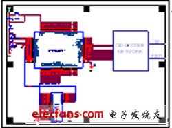
Terminal system architecture based on W925EP01
The terminal only needs the MCU + Memory architecture, and a simple CID amplifier circuit is built externally to realize the operation of the entire remote upgrade system.
As shown in the figure below, MCU W925EP01 uses P5 and P6 as the address bus, P7 as the data bus to connect with the external RAM, and the remaining P0 to P4 ports are compatible with the previous W925 series.
Workflow of remote upgrade system
After calling the terminal, the main control end checks whether the communication is connected through the user-defined handshake protocol. After confirming the connection, the main control end sends the code of the upgrade program and the terminal receives it. After the code is sent and the terminal checks and receives it successfully, the terminal Hang up the connection with the main control end and perform the ISP self-update action.
Workflow of main control terminal during remote upgrade
When remote upgrade is required, the main control end sends an update command to the terminal, waits for the terminal to receive and return the permission to send signal, and sends the terminal update program code through FSK.
Terminal workflow during remote upgrade
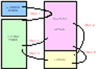
Definition: The area where W925EP01 runs normally program storage space is APROM, and the program storage space that runs ISP update program is LDROM.
In normal working state, APROM runs the work program. When a CID signal arrives, W925EP01 first detects whether the ISP upgrade command (STEP 1) sent by the master is confirmed, and then W925EP01 jumps to the LDROM area to run (STEP 2), and then checks whether the communication is successfully connected , LDROM receives FSK data and stores it in the off-chip data storage space (STEP 3). After verifying that the data is received and stored correctly, hangs up the connection with the main control end and writes the data in the off-chip data storage space to APROM (STEP 4), the programming code is completed, W925EP01 jumps back to APROM work, and the terminal ISP self-update work is completed. The diagram is as follows.
Summary of this article
The system remote upgrade program based on fixed phone line constructed by W925EP01 has simple upgrade process control and the cost is much lower than other remote upgrade programs. It is suitable for large-scale remote upgrade systems. As a cheap solution, it is used in various systems based on fixed telephone line network such as community security, home school, etc., which is highly competitive in the market.
Bulkhead Lamp,Led Bulkhead Lamp,Round Bulkhead Light,Bulkhead Ceiling Light
Changxing Fanya Lighting Co.,Ltd , https://www.fyledlights.com