The basic working principle of plc
The basic working principle of plc
1. Scanning technology When PLC is put into operation, its working process is generally divided into three stages, namely input sampling, user program execution and output refresh. Completing the above three stages is called a scan cycle. During the entire operation, the CPU of the PLC repeatedly executes the above three stages at a certain scanning speed.
(1) Input sampling stage In the input sampling stage, the PLC sequentially reads all input states and data in a scanning manner and stores them in the corresponding units in the I / O image area. After the input sampling is completed, it shifts to the user program execution and output refresh phase. In these two stages, even if the input status and data change, the status and data of the corresponding unit in the I / O map area will not change. Therefore, if the input is a pulse signal, the width of the pulse signal must be greater than one scan period to ensure that the input can be read in any case.
(2) User program execution stage In the user program execution stage, the PLC always scans the user program (ladder diagram) in order from top to bottom. When scanning each ladder diagram, the control circuit composed of contacts on the left side of the ladder diagram is always scanned first, and logical operations are performed on the control circuit composed of contacts in the order of left first, then right, and then top and bottom. , And then refresh the state of the corresponding bit of the logic coil in the system RAM storage area according to the result of the logic operation; or refresh the state of the corresponding bit of the output coil in the I / O image area; or determine whether to execute the ladder diagram The specified special function instructions.
That is, during the execution of the user program, only the status and data of the input point in the I / O image area will not change, while other output points and soft devices are in the I / O image area or the system RAM storage area. Both state and data may change, and the ladder diagram listed above, the program execution results will affect the ladder diagrams that are used below for those coils or data; on the contrary, the ladder diagrams listed below, which The status or data of the logic coil being refreshed can only affect the programs arranged on it until the next scan cycle.
(3) Output refresh stage When the scanning user program ends, the PLC enters the output refresh stage. During this period, the CPU refreshes all output latch circuits according to the corresponding status and data in the I / O image area, and then drives the corresponding peripherals through the output circuit. At this time, it is the real output of PLC.
The same several ladder diagrams have different arrangement order and different execution results. In addition, the results of the scanning user program are different from the results of the parallel operation of the hard logic of the relay control device. Of course, if the time taken by the scan cycle is negligible for the entire operation, then there is no difference between the two.
In general, the PLC scan cycle includes self-diagnosis, communication, etc., as shown in the following figure, that is, a scan cycle is equal to the sum of all times of self-diagnosis, communication, input sampling, user program execution, and output refresh.
Programmable controller, English called ProgrammableLogicController, referred to as PLC. PLC is an electronic controller based on an electronic computer and suitable for industrial field work. It originated from the relay control device, but unlike the relay device, it is controlled by the physical process of the circuit, but mainly by running the program stored in the PLC memory to perform the conversion of input and output information to achieve control.
PLC is based on electronic computer, but it is not equivalent to ordinary computer. Generally, computers change information in and out, and only consider the information itself, as long as the human-machine interface is good. The PLC also needs to consider the reliability, real-time nature of information entry and exit, and the use of information. Special consideration should be given to how to adapt to the industrial environment, such as ease of installation and anti-interference.
1.1 Key Points for Controlling The transformation of input and output information and reliable physical implementation can be said to be the two basic points for PLC control.
The input and output information conversion is realized by running the program stored in the PLC memory. The PLC program includes not only the manufacturer's system program (cannot be changed), but also the application (user) program developed by the user. The system program provides an operating platform, and at the same time, it also performs the necessary public processing for the reliable operation of the PLC program and the conversion of signals and information. The user program is designed by the user according to the control requirements. What kind of control requirements, there should be what kind of user program.
Reliable physical realization mainly depends on input (INPUT) and output (OUTPUT) circuits. PLC's I / O circuits are specially designed. The input circuit should filter the input signal to remove high-frequency interference. Moreover, it is electrically isolated from the internal computer circuit, and the connection is established by the optical coupling element. The output circuit is also electrically isolated inside and outside, relying on optocoupler components or output relays to establish contact. The output circuit also needs power amplification to drive general industrial control components, such as solenoid valves, contactors, etc.
There are many I / O circuits, and each input point or output point must have an I or O circuit. PLC has multiple I / O points, and generally there are as many I / O circuits as there are. However, since they are all composed of highly integrated circuits, they do not occupy a large volume.
The input circuit monitors the input status at all times and temporarily stores it in the input register. Each input point has a corresponding scratchpad that stores its information.
The output circuit transmits the information of the output latch to the output point. The output latches and output points are also in one-to-one correspondence. The input temporary registers and output latches here are actually the registers of the PLC processor I / O port. They exchange information with computer memory via a computer bus and are mainly implemented by running system programs. Read the information entered into the temporary memory into the PLC's memory, called input refresh. The PLC memory has a specially developed mapping area for storing input information. Each corresponding bit in this area is called an input relay, or soft contact. These positions are set to 1, indicating that the contact is on, and set to 0 for the contact to be off. Since its state is obtained by input refresh, it reflects the input state.
The output latch also corresponds to the output mapping area in the PLC memory. An output latch also has a memory bit (bit) corresponding to it, this bit is called the output relay, or output coil. By running the system program, the state of the output relay is mapped to the output latch. This mapping is also called output refresh. The output refresh is mainly realized by running the system program. In this way, the program that the user wants to compile is only the conversion of the input mapping area to the output mapping area in the memory, especially how to convert the input timing into the output timing. This is a data and logic processing problem. Because PLC has a powerful command system, it is completely possible to write a program that meets this requirement, and it is also relatively easy.
1.2 Realization of control process Simply put, the process of PLC control is generally:
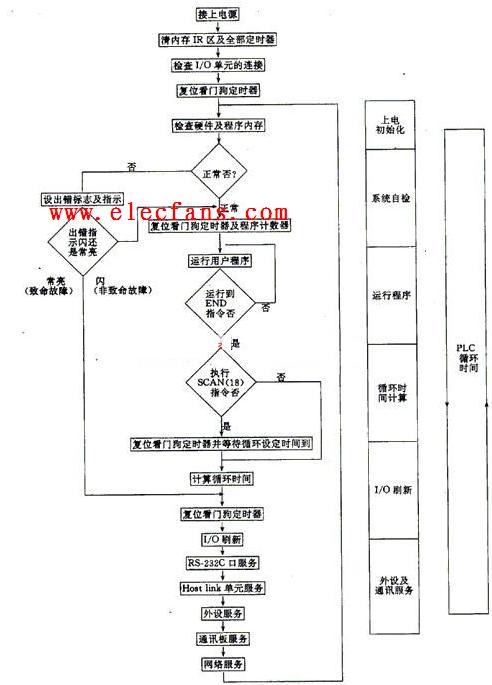
Figure 1.1 Typical PLC start-up process Input refresh-re-run user program-re-output refresh-re-input refresh-re-run user program-re-output refresh ... Never stop and repeat.
The flow chart shown in Figure 1.1 reflects the above process. It also reflects the temporal relationship of information.
With the above process, it is obviously possible to realize control with PLC. Because: with input refresh, the input information monitored by the input circuit can be stored in the input mapping area of ​​the PLC; after running the user program, the output mapping area will get the transformed information; and after the output refresh, the output latch will reflect The state of the mapping area is output, and the corresponding output is generated through the output circuit. Since this process is cyclically repeated without stopping, the output always reflects the change of the input. Only the response time is slightly lagging. Of course, this lag should not be too large, otherwise, the control achieved is not so timely, and the meaning of control is lost.
For this reason, the working speed of PLC should be fast. Fast speed and short execution time are the basis of PLC control. In fact, its speed is very fast. It takes only a few microseconds, tens of microseconds to execute an instruction, and only a few tenths, or zero microseconds. And this speed is constantly improving.
The process shown in Figure 1.1 is a simplified process, the actual PLC working process is more complicated. In addition to I / O refreshing and running user programs, some common processing work is also required.
Public processing work includes: cycle time monitoring, peripheral service and communication processing.
The purpose of monitoring the cycle time is to avoid "dead loop" and prevent the program from being executed repeatedly. The way is to use "Watchdog" (Watchingdog). As long as the cycle times out, it can report an alarm or handle it accordingly.
Peripheral service is to allow the PLC to accept the programmer's operation on it, or to output data to an output device such as a printer through an interface.
Communication processing is to realize information exchange between PLC and PLC, or PLC and computer, or PLC and other industrial control devices or intelligent components. This is also the need to enhance PLC control capabilities.
In other words, the actual PLC work process is always: public processing-I / O refresh-running user programs-and then common processing-... repeating repeatedly.
1.3 The way the programmable controller realizes the control The scan mode is realized by this kind of continuous repetitive running program. It is a way of real-time control by computer. In addition, the computer is used to control and interrupt mode. In the interrupt mode, the control that needs to be processed first applies for an interrupt, and the program that is running after being stopped responds to the operation, and instead handles the interrupt work (runs the interrupt service program). After the interrupt is processed, it returns to the original program. Which control needs to be processed, whichever is applied for interruption. Which does not need to be dealt with will be ignored. Obviously, the interrupt mode is different from the scan mode.
In the interrupt mode, the computer can be fully utilized, and urgent tasks can be handled in a timely manner. But what if there are several tasks to be processed at the same time? The ones with higher priority are easier to handle, but the ones with lower priority? There may be things that cannot be taken care of. Therefore, the interruption method is not suitable for daily use on the job site.
However, when the PLC mainly uses the scanning method, the interrupt method is not excluded. That is, a large amount of control uses the scanning method, and the individual urgently needed processing allows the program running this scan to be interrupted and turned to deal with it. In this way, all controls can be taken care of, and individual emergency can also be handled.
The actual working process of PLC is more complicated than that described here. There are still some theoretical problems in analyzing its basic principles. If the relevant personnel can study the input and output conversion, physical implementation-information processing, I / O circuit-space, time relationship-scanning method and the interrupt method introduced above, as a way of thinking, understand it, It is easy to understand how PLC realizes the control, and it is also easy to grasp the main points of PLC basic principles.
We are among the renowned manufacturers and suppliers of wide range of Solar Street Lights that are available with different power ranges and consist of sodium vapors, LED's and CFL's. Our lights can easily operate in misty and foggy conditions. These products are resistant to adverse weather conditions and requires minimum maintenance. our entire product range can be customized as per the clients as per the clients` requirement and preference. Quality tested, In compliance with international quality standards,Feasible rates.
Other LED Street Light,LED Street Light,Street Lights,Street Light LED
Shenzhen Ri Yue Guang Hua Technology Co., Ltd. , https://www.ledlightinside.com