Design scheme of embedded low power mobile ECG monitoring system
1 Introduction
With the continuous development of information technology and medical level and the continuous improvement of people's living standards, more and more people have put forward higher requirements for personal and family health care, hoping to keep abreast of their physical health, and Find illnesses and solve problems as soon as possible. At present, the traditional Holter system is bulky and the inconvenience of use is also inconvenient for people's daily use. Therefore, using the latest wireless sensor network and microprocessor technology, a mobile ECG information acquisition and monitoring system with long-term online and wireless mobile monitoring capability is designed to have high practical value and market potential.
This paper designs and develops a wireless sensor ECG information monitoring system by studying the main characteristics of human ECG signals and the actual monitoring application requirements. The system collects and processes ECG signals through smart electrodes embedded in underwear. The ECG data is sent to the Android intelligent monitoring terminal for storage, management and analysis of the received data through the Bluetooth wireless data network that has become the standard for mobile devices.
2. The overall structure of the system design
The overall structural block diagram of the system is shown in Figure 1. It includes an ECG lead embedded in the underwear, a smart electrode signal processing circuit module, and an intelligent Android terminal application equipped with Bluetooth. The smart electrode signal processing module includes an analog signal conditioning circuit and a microprocessor. The circuit and the wireless Bluetooth network module and the body temperature sensor and the blood oxygen probe can be extended on the module to extend the life health monitoring parameters.
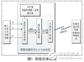
The system first sends the ECG signal collected by the lead electrode embedded in the underwear to the signal processing circuit module in the smart electrode, and is filtered and amplified by the analog signal conditioning circuit.
After the signal is conditioned, it is sent to the main control microprocessor for analysis and preprocessing via A/D conversion. Then, the wireless Bluetooth network is sent to the intelligent Android terminal application equipped with Bluetooth through the wireless channel for diagnostic analysis and monitoring display. When an anomaly is found, the terminal application issues an alert and can send the results to the telehealth via the mobile internet.
Since the analog signal conditioning circuit in the smart electrode is not the part of the system design, this paper mainly introduces the data analysis preprocessing, wireless Bluetooth communication and Android terminal application design.
3. Intelligent electrode control software design
This system uses TI's MSP430G2553 ultra-low-power microprocessor to build a central processing unit. The MSP430 microcontroller excels in low power consumption, supports fast sleep, saves a lot of system power consumption, and works stably under harsh conditions. The G2553 model MCU is loaded with a self-designed critical feature extraction algorithm to meet the design requirements.
Figure 2 shows the flow chart of the intelligent electrode control software.
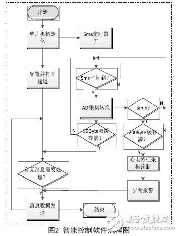
The main process is that after the signal conditioning circuit preprocesses the ECG analog signal, the ultra-low-power microprocessor collects and converts the analog data through a built-in 10-bit AD conversion module (sampling accuracy of 3mV) with a sampling period of 5ms. After the converted data is taken up to 8 bits, it is sent to the Bluetooth module through the wireless Bluetooth network through the asynchronous serial port (UART).
4.Android terminal application design
4.1 Bluetooth data receiving module design
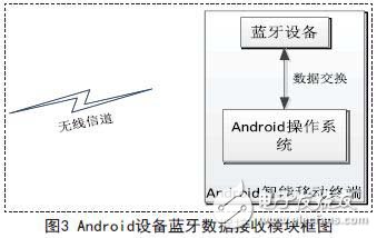
Modern social intelligent mobile terminals have become an indispensable part of people's lives. At present, most of the smart mobile terminals represented by mobile phones are based on the Android system and equipped with Bluetooth devices, so in order to meet the needs of people's daily life. Develop applications using a smart Android mobile terminal configured with Bluetooth as a data processing and diagnostic platform. The application is developed in the Java language. Figure 3 shows the design of the Bluetooth data receiving module of the Android device.
4.2 Android device Bluetooth transmission implementation
Bluetooth communication uses the C / S communication mode. At the time of design, the Bluetooth of the receiving end (Android device) is used as the client, and the transmitting end (smart electrode) is used as the server side.
When Bluetooth is connected to each other, the Socket (socket) mechanism commonly used in data communication is utilized. After the sockets at both ends are connected to each other, the application of the sender and the receiver can send the data to its own socket and obtain the data from the socket. The sockets of both parties are sent and received as the connection relay station. data. The following describes the implementation process of the Bluetooth receiving software on the Android device.
First, the Bluetooth function of the A ndroid terminal is turned on, and the Android terminal Bluetooth device as a client needs to actively search for surrounding Bluetooth devices. This search process requires a broadcast mechanism, that is, the search initiator needs a broadcast receiver for receiving search information. The specific steps are as follows: First, define a class that inherits BroadcastReceicer. The instance generated by this class has the ability to receive information and obtain the required information, such as Bluetooth device name and MAC address. After setting, the broadcast receiver only responds to the message that the Bluetooth device is found and the Bluetooth search ends, and the registration of the broadcast receiver in the application is completed. When the user is using, he only needs to click the "Search" button, and the terminal device starts searching for the surrounding Bluetooth devices, and the entire search process takes 12 seconds. During this process, the local Bluetooth adapter will search for all Bluetooth devices that can be connected around, and display these search results in a list on the screen for selection. Before the connection starts, first turn off the Bluetooth search function.
There is a BluetoothSocket class in the system library. Using this class to generate the corresponding instance is the Bluetooth socket of the receiving end. If the Bluetooth is connected as a server, the system class BluetoothServerSocket is used to generate the socket object. Before connecting, you need to set the UUID in advance, and then the Android smart terminal initiates the connection request. Here, you need to call the connect() method in the BluetoothSocket class. As the Bluetooth device on the server side monitors the connection request, it will verify whether its UUID is consistent with its own. Once the verification is passed, the connection can be completed. It is important to note that in this process, the connection process is a blocking call process. In order not to affect the work of the main thread, a separate thread is needed to connect.
HIGH QUALITY:Made of only the highest quality materials and built to last! Our chargers are gauranteed to match the original brand name chargers' quality.
EASY TO USE: Simply plug the charger into a wall outlet and then directly into your scooter.
The charger protected: Short circuit protection/ over current protection/ over voltage protection; red light -- charging, green light -- charge OK, it stop automatically when the battery is full. Warm Tips: To avoid the temperature of your charger too high, please do not charge too long.
The shell is made by high-quality plastic, smooth appearance with no impurities. Good safety performance, more reliable for you to use. Red light means charging; Green light means fully charged or disconnect.Aviation Plug Scooter Charger,Power Scooter Charger,Li-Ion Battery Charger
Shenzhen Waweis Technology Co., Ltd. , https://www.waweis.com