Low-energy power supply design for starting and stopping a car
With the rapid development of the city, most people own their own cars, which also makes traffic congestion, and the car stops and stops at the peak period will consume a lot of energy, not only waste but also pollute the environment. Therefore, the "start and stop" function in the automotive system was introduced, but this system also brought some unique engineering and technical challenges to the automotive electronics. The Power Supply design in the vehicle start-stop system is a big problem. This article introduces a low-energy power supply design for car start-stop.
This article refers to the address: http://
In order to control fuel consumption, many car manufacturers have implemented "start and stop" functions in the next generation of cars, and a large number of such cars have begun to take the road. These systems shut down the engine when the car is stopped, and when the foot moves from the brake pedal to the accelerator pedal—or automatically re-start the engine when the clutch pedal is released using the manual gear to re-energize the power. This feature is very helpful in reducing fuel consumption during peak hours of city travel and stop-and-go.
However, such systems also present some unique engineering challenges to automotive electronics because the battery voltage can drop to 6.0V or less when the engine is restarted. In addition, typical electronic modules include a reverse polarity diode that protects the vehicle's circuitry when the car is lined up and accidentally reverses the line. This diode will reduce the battery voltage by another 0.7V, so the voltage available for downstream circuits is only 5.3V or lower. Since many modules still need 5V power supply, there is basically no margin, and it is difficult to ensure the normal operation of the circuit.
Boost power supply
One method is to boost the power supply, that is, input a lower voltage and output a higher voltage. At present, many suppliers use some type of boost power supply at the front end of the electronic module, so that the electronic module can work normally even under the step-down condition caused by the start-stop system.
As with most engineering problems, there are many ways to solve problems. If the battery voltage at the input only drops to 6V, then the simplest and simplest solution is to find a low-dropout linear regulator that works with a dropout voltage of less than 0.3V. This method is suitable for modules with lower current requirements, but this method is not suitable for modules with higher current requirements.
Another method is to replace the standard PN junction diode for reverse polarity protection of the front-end battery with a Schottky diode or a P-channel MOSFET. The forward voltage drop of a Schottky diode is about half that of a standard rectifier, so it can increase the differential margin of a few tenths of a volt. Switching to a Schottky diode is fairly straightforward because it can be mounted directly on the same PCB pad as a standard diode without modifying the layout.
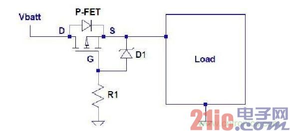
Figure 1: Battery reverse polarity protection with P-FET.
However, the use of P-channel MOSFETs requires modification of the PCB and the addition of additional circuitry.
Figure 1 shows that three components are required: a P-FET, a Zener diode, and a resistor. The P-FET needs to be sized to handle the voltage applied to the input of the module and the required load current. In addition, the thermal requirements of the system must be carefully considered because the FET power consumption is equal to the square of the current multiplied by the on-resistance of the FET. Zener diodes prevent MOSFET gate oxides from being damaged by overvoltage conditions. Most P-FETs can withstand voltages from 15V to 20V from the gate to source connection, so the Zener diode is chosen to be clamped before this voltage point. The resistor pulls the gate to ground for turning on the P-FET, but it must also be adjusted to the appropriate value. The resistance should not be too small, too small will allow too much current to flow through the Zener diode, causing power consumption problems. However, the resistance value should not be too large, and if it is too large, the P-FET cannot be reliably turned on. In summary, the guiding idea of ​​this method is to reduce the voltage drop across the drain-to-source connection. Voltage dips below 5V
One or a combination of the above solutions may solve the problem for a given application. But what happens if the input voltage really drops below 5V? Some manufacturers have found that the voltage drops to 4.5V under "cold start" conditions. If this happens, you will need to use a Switching Power Supply to boost the input voltage. The three most common switching power supplies are the boost supply, the buck/boost supply, and the SEPIC supply.
The boost supply uses an inductor, an N-FET, a diode, and a capacitor. This is the simplest design, but there are some drawbacks. If the output is shorted, there is no way to protect it, since the input to the output is a straight-through path. In addition, when the input voltage rises above the output voltage setpoint, there is no way to prevent the output voltage from rising at the same time because the input voltage can pass through the inductor and the diode through the output.
For example, most modules on a car must pass the load test. A voltage spike is generated during this test and applied to the Vin terminal. In the case of a boost supply, this voltage spike will propagate directly to the output. Therefore, if a 40V spike is propagated, all circuits connected to the Vout terminal must be able to withstand this voltage.
Another possibility is the in-phase buck/boost design. This solution uses only one inductor and one capacitor, but requires two switches and two diodes. However, this approach allows the designer to prevent the output voltage from continuing to rise when the input voltage is higher than the output voltage. This solution also prevents the effects of output shorts by cutting off the first switch (FET1). The disadvantage of this design is efficiency, because both diodes and both switches are worn out.
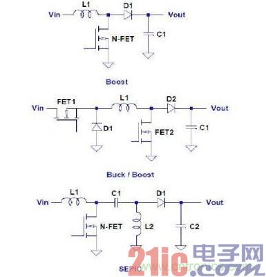
Figure 2: Various boost power supplies.
The layout of the single-ended primary inductor converter (SEPIC) is very similar to the direct boost converter, except that it adds a ground-to-ground inductor and a DC-blocking capacitor. The advantage is that there is no longer a short circuit at the output because the output is now A DC blocking capacitor is connected in series. The output is also no longer affected by the input voltage and can therefore be lower or higher than the input voltage. It should be noted that, as indicated by all switching topologies, a battery reverse polarity protection mechanism is still required because the reverse current will still flow back from ground to the input voltage through the body diode of the FET.
In summary, there are many issues to consider when using a start-stop alternator system. This article is a brief discussion of the power supply for electronic modules. There are actually other factors to consider. For example, internal and external illumination can dim when these voltages drop. Although the internal lights are irritating, they are not critical, and the brake lights and headlights directly affect safety, so the corresponding power solution is needed to keep them working. Fortunately, there are already solutions on the market that can solve these problems.
SP300VAC600W is a switching mode single-channel output high-precision AC Power Source, it`s cost effective and fully programmable for both basic frequency conversion and advanced AC power line or DC power disturbance test applications. This Ac Power Supply adopts high speed DSP+CPLD control, high frequency PWM power technology and active PFC design to realize AC/DC stable output.
APM AC Output Power Supply is featured with high power density, high reliability and high precision, meanwhile it possesses operation interface of touch screen and keys manually. It is able to analog output normal or abnormal input for electrical device to meet test requirements.
Some features as below:
- 4.3"large touch color screen
- AC+DC mixed or independent output mode
- Capable of setting output slope/phase angle
- Built-in IEC standard test function
- Built-in multiple protections
- Built-in power meter
- Support impedance function
- Support for LIST/PULSE/STEP mode & Transient mode
- Standard RS232/RS485/USB, Optional GPIB//LAN
- Support harmonics/inter-harmonics simulation and measuring function
- Support for USB data import/export and scree nap from front panel
600W AC Power Supply,Variable AC Power Supply,Portable Ac Power Source,Ac Voltage Source
APM Technologies (Dongguan) Co., Ltd , https://www.apmpowersupply.com