Improve energy efficiency by optimizing converter FET switching
 In computing and consumer electronics, efficiency has improved significantly, with emphasis on AC/DC conversion. However, with the advent of 80 PLUS, Climate Savers, and EnergyStar 5 specifications, designers began to realize that both AC/DC and DC/DC power systems needed improvement.
 AC/DC average system efficiency is about 65%, while DC/DC average system efficiency is 80%, so it's not hard to understand why everyone focuses on AC/DC systems. However, it is time to review the DC/DC system and find new ways to improve efficiency.
DC/DCs in computing, communications, and consumer applications are responsible for converting, managing, and distributing power, powering graphics, processor chips, and memory. All of these functions are faced with the need to improve performance, and therefore more than ever All need more efficiency. There have been studies utilizing the latest advances in MOSFETs and advanced thermal packaging techniques to increase the efficiency of existing switching circuits and related power transistor devices.
Careful selection of power components, especially onboard synchronous buck converters, can dramatically improve the power density, efficiency, and thermal performance of the new platform. For example, if 500,000 servers are fully compliant with 80 PLUS energy requirements, the energy savings will be enough to supply more than 377 000 households.
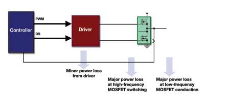
Circuit and lossy buck or synchronous buck circuits are heavy-duty components of all low-voltage DC/DC power management systems, and the main power loss in all synchronous buck circuits comes from switching and conduction losses in MOSFETs.
A common buck rectifier (VRM) can be found in any desktop computer. As shown in Figure 1, this rectifier can provide more than 25A current and 1.2V output at full load. Therefore, one MOSFET will be in the main path or in the high-side slot, and two parallel MOSFETs will be in the flywheel or bottom slot. Stepping down the 12V input to a 1.2V output, the duty cycle is 10%, so the high-side MOSFET will adjust for low switching losses, while the low-side MOSFET pair will minimize RDS(ON) to minimize conduction losses. .
The typical peak efficiency of a multi-phase VRM VCORE scheme implemented by discrete drivers and MOSFETs is 90%, occurring at 10A per phase rated current, and at full load 30A, the efficiency is reduced to 85%. For today's designers, a complete VRM system typically has an output power of 100W and an efficiency of 85%, which means that the power loss is 15W.
Step-by-step improvement of silicon-based MOSFETs MOSFET manufacturers mainly use two approaches to optimize process development. First, in order to improve the switching characteristics (switching speed) of the products, they implemented an advanced gate structure design that reduced the gate charge (Qg) effect. The second is to increase the cell density, that is, on the same size wafer, the on-resistance is significantly reduced. RDS(ON) and current are the two determinants of MOSFET conduction losses. The calculation formula for conduction loss is simple:
Ploss=I2×RDS(ON) Conduction loss Ploss=1/2V×I×(Tr+Tf)×F Switching loss
Merchandising Display Box,Perforated Display Box,Gift Card Organizer,Acrylic Store Candy Box
Yuefeng Display Product Co., Ltd. , http://www.mw-acrylicdisplay.com