Analysis: How to build self-monitoring intelligent LED lamps
Editor's note: Large lighting equipment also needs to be “intelligentâ€. It is a expectation for a new generation of LED luminaires to have the luminaires have the ability to communicate with the "parent" controller, monitor their condition, adjust the operating mode based on the monitoring results, and be able to enter a safe state after failure. This article will explore some of the "smart" choices for LED luminaires and their implementation steps.
Light-emitting diodes have long been used as low-cost indicator lights for a variety of electronic products. They are now powerful sources of light for interior lighting, signage, display and decorative lighting applications. Compared to incandescent and fluorescent lamps, the energy consumption due to the same brightness is much smaller, and the status of LEDs is increasing. Energy is one of the hottest topics of the century and will soon be one of the most important issues for designers around the world to consider.
For luminaire manufacturers, the use of LEDs has many advantages. However, the number of vendors trying to catch up with the LED wave as early as possible is so great that product differentiation is very important. In addition, when lighting and labor costs become the main issues to be considered in design, large-scale lighting equipment also needs to be “intelligentâ€. It is a expectation for a new generation of LED luminaires to have the luminaires have the ability to communicate with the "parent" controller, monitor their condition, adjust the operating mode based on the monitoring results, and be able to enter a safe state after failure. This article will explore some of the "smart" choices for LED luminaires and their implementation steps.
Enter low voltage blocking:
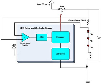
The input voltage to the drive system is typically a DC voltage. The power supply is provided by an off-line AC-DC converter or bus. In addition to powering the LED driver, the power supply is also used to power the controller in the system (which needs to be converted to a 5V or 3.3V voltage suitable for the controller). The controller power supply is typically designed to operate when the input voltage is slightly above the required output voltage. For example, a 5V regulator will start working when the input voltage reaches 6-7V. However, the steady state of this power supply can be a string of LEDs consisting of 5-6 LEDs, and a 24V power supply with 1A of current per string. Once the controller is powered up, the controller assumes that the power supply is available and turns on the LED drive system (assuming it is configured), and then the LED drive system will attempt to enter normal operation. If the input voltage is only 10V at this time, the current supplied by the power supply will be much larger than the current in the steady state, and the system will collapse due to this sudden current surge. This excess current demand can also exceed the rated capacity of cables, connectors, and other components of the input power supply, which can cause permanent damage to the system.
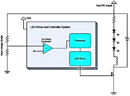
To avoid this, the system should have a "low voltage lockout" function. The hardware used is a resistor divider that gradually reduces the input voltage to the range that the controller's input can withstand. The input is internally connected to the comparator. The action of the controller (firmware) should be designed so that the power section is only enabled when the input voltage exceeds the threshold for normal operation. In addition, the voltage system is not activated as soon as the comparator is turned on. The firmware should poll the output of the comparator to check if this state is consistent (because the comparator is part of the combinatorial logic) and then power up the system. Figure 2 is a hardware schematic (schematic diagram) for implementing this function.