Powering the high-speed CAN transceiver with a charge pump
In the past few decades, from the development trend of the automobile industry, the requirements for comfort, efficiency and environmental friendliness of automobile manufacturing have been continuously increased, and the expectations for performance and safety of automobiles have also been continuously improved. Driven by this trend, the number of electronic subsystems in the car and the wiring connecting these subsystems has increased significantly. The increase in cables has led to an increase in the weight of the car and, of course, an increase in cost. However, in the early 1980s, Bosch introduced the CAN bus network, which is widely used in the automotive industry because it effectively reduces the complexity of line connections, reduces cable weight and saves costs.
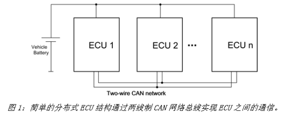
The shift in automotive manufacturing from centralized control systems to distributed control systems has helped automakers achieve their goal of reducing vehicle weight and cost. The centralized control system connects all actuators, sensors and switches to the control system via a large number of cables, while the distributed management system places the electronic control unit (ECU) in the position to be controlled and communicates with each other via the bus system (eg two lines) CAN bus network) (Figure 1).
A CAN network consists of multiple transceiver modules that are linked by a pair of buses. Each module is a CAN transceiver that supports the physical layer interconnection between the protocol controller (microcontroller, state machine or other processing engine within the module) and physical media (cables). This new CAN bus design requires rapid standardization to ensure proper communication between ECUs from different manufacturers. ISO (International Organization for Standardization) first standardized its definition in 1993 and made further amendments in 2003 and 2007. The current ISO 11898 standard has been adopted by original equipment manufacturers (OEMs) as current standards for CAN communication within all vehicles.
To meet ISO standards and provide the correct bus level, most CAN transceiver bus drivers require a 5V supply. However, the main power supply of an electronic system usually cannot meet the power requirements of the subsystem. In this case, the supplied system power supply usually cannot directly power the CAN transceiver. For example, the system may only provide a 3.3V power supply. Sometimes it is impossible to accommodate the most suitable power supply due to space constraints; sometimes it is impossible to generate 5V directly from the battery due to heat generation, especially in CAN communication systems with high battery voltage (eg, when using a dual battery in a car, or 24V truck system).
A voltage converter can be used to generate the required supply voltage, and a charge pump is usually the best choice for low power, low cost, low cost designs. It does not require expensive inductors or additional semiconductor devices and is easy to use.
. Choice of charge pump
Transceiver power supply
There are simple, well-functioning CAN transceivers on the market. Some transceivers require a single power supply, while others require multiple power supplies. In order to enable interoperability between modules from different ECU vendors and to achieve high speed CAN communication in accordance with ISO 11898, most modules require a 5V supply that meets the maximum tolerance requirements.
Some transceivers also come with built-in I/O level adapters. Using the power of the protocol controller (acting on the transceiver's separate power supply pin), the level adapter scales the transceiver's I/O level to the controller level. As a result, the transceiver can be directly connected to a controller operating below 5V without any glue logic.
The low-power management transceiver supports local and remote wake-ups, so there is another power supply pin. This pin must be continuously powered by the car battery and consumes very little current. The ECU therefore requires that the high speed CAN bus must remain active even when the ignition key is "off".
For a description of the function of the other pins of the CAN transceiver, please refer to the data sheet of the selected device.
2. Supply current
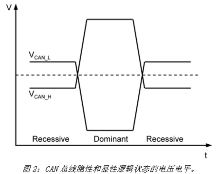
The CAN bus is usually in one of two logic states: recessive or dominant (Figure 2). In normal communication mode, the transceiver requires the maximum input current in the dominant state, and the input current required in the recessive state is the smallest. The current consumed by the I/O level adapter and remote wake-up function is negligible because they typically consume the current of the microcontroller power supply and the car battery, and the value is very small.
When the bus fails, the supply current will increase significantly, especially when the CAN_H line is shorted to ground. Most transceivers limit the short circuit current to a specific maximum. In order to prevent the power supply voltage from dropping, it is better to define the output current specification of the charge pump according to the current requirement in this case.
Based on the above considerations, in order to provide the proper power supply to the CAN transceiver, the charge pump must maintain a 5V output voltage and meet the nominal voltage tolerance in the transceiver data sheet. The minimum output current must support the CAN_H short circuit to ground.
Powering the MAX13041 Transceiver with the MAX1759 Charge Pump
A variety of traditional CAN transceivers and charge pump devices can be found on the market. This article focuses on the design of the MAX13041 HS CAN transceiver and the MAX1759 buck/boost regulated charge pump to address transceiver power issues. The transceiver is powered by the VCC pin. To support standard ISO 11898 CAN communication, VCC must be maintained between 4.75V and 5.25V (nominal operating voltage range). This voltage establishes the correct communication signal between the bus (CAN-H, CAN-L) and supplies the receiving circuit when the IC is in normal operating mode.
The transceiver's VI/O input enables the interface circuitry of the 3.3VI/O microcontroller to establish the correct level at the receive/transmit (RxD/TxD) level of the controller and transceiver. Of course, when communicating with a 5V controller, the VI/O pin can also be powered from a 5V supply.
The VBAT pin (usually connected to a car 12V battery) powers the wake-up detection circuitry with very low quiescent current. Based on the CAN bus information, this pin can control the MAX13041 to wake from Sleep mode. For a detailed description of other pins, please refer to the MAX13041 data sheet.
In normal communication mode, the maximum input current (VCC pin) required by the MAX13041 in the dominant state is 80mA, and 10mA in the recessive state (Figure 2). The current flowing into VI/O and VBAT is negligible. When the bus fails, the VCC supply current will increase significantly, especially when the CAN_H signal line is shorted to ground. The MAX13041 limits the short-circuit current to IO(SC) = 95mA.
Based on the above considerations, in order to meet the power requirements of the CAN transceiver, the charge pump must have a stable 5V output voltage to ensure compliance with the voltage tolerance requirements, the minimum output current is 95mA.
Charge pump requirement
The MAX1759 architecture allows the input voltage to be higher or lower than the regulated output value. In this application, the charge pump only works as a boost converter. When VIN is below VOUT, the charge pump operates as a regulated boost voltage doubler. At light loads, the charge pump only switches when it needs to maintain the load's supply energy, consuming very little quiescent current. At light loads, the output voltage ripple does not increase.
For a detailed description of other features of the charge pump, please refer to the MAX1759 data sheet.
2. Realize the 3.3V solution
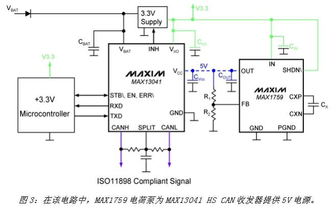
As can be seen from the circuit of Figure 3, it is very simple to power the MAX13041 with a charge pump. Simply connect the MAX1759 to the VCC input of the CAN transceiver (shown by the dashed blue line) to produce a 5V output voltage that meets tolerance and output current requirements. This configuration allows other circuits to be powered by low voltage. In this example, an external 3.3V supply (green) powers the charge pump (IN), the microcontroller, and the transceiver's VI/O level shifter. Pull the /SHDN of the charge pump high to place the device in the ON state. The MAX1759 data sheet details the choice of input/output (CIN, COUT) and flying capacitor (CX).
Smart down light with both warm light and RGB colorful light, it can meet the daily lighting and ambient lighting, high efficiency and energy saving, light source is stable and without strobe. Three color temperatures can be choosed for white lighting, 3000K, 4000K and 65000K. The color, brightness and RGB lighting auto-cycle mode can be controlled on the App. Three sizes of down lights for customer`s choice, small , middle and big sizes can meet different requirements, and the installation is very easy.
Product Parameters
Lamp Power: 9W
Working Voltage: AC110-240V
Frequency: 50-60HZ
Lumen: 805LM
Color: RGB+CCT
Protocol: Bluetooth Mesh
Wireless Transmission: 20m
Control way-APP
The light color, brightness, cycle mode and timing can be controlled by App.The App are developed on the most advanced Bluetooth Mesh technology. [LinkupHome" App can be downloaded in the App store or Google Player, then you can control our product without any complicated steps. The App is stable, easy control and multifunctional.


The advantages of Bluetooth Mesh are fast connect, low power consumption, no password required and Ad-Hoc Network. No need WIFI and hubs, as long as you have a Bluetooth-enabled smart phone, you can experience the smart light. When you install several smart down lights, the self-organizing network function can make the signals free connect, break the limitation of distance.

Small Size Downlight,Small Diameter LED Downlights,Very Small Downlights,Small LED Downlight
Ningbo Homey Photoelectric Technology. Co., Ltd , http://www.linkuphome.com