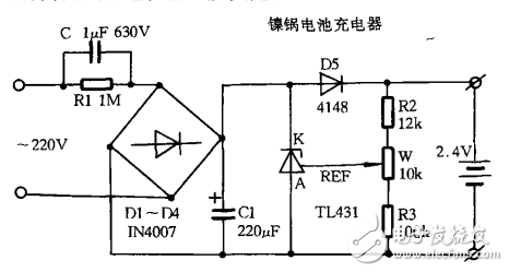
Making a simple charger circuit with TL431
The TL431 is an integrated circuit that functions as an adjustable shunt regulator, making it ideal for creating a basic and cost-effective charging circuit.
Working Principle:
The circuit diagram illustrates the setup. It begins with a step-down transformer that reduces the AC voltage from the mains. This low-voltage AC is then rectified using a bridge rectifier and filtered by a capacitor to produce a smooth DC output. This DC voltage is used to charge two nickel-tin batteries through diode D5. The charging current and voltage level are controlled by a variable resistor W, allowing for fine-tuning of the charging process.

The TL431 is known for its high stability, excellent switching performance, and ability to handle relatively high currents. It has a fixed reference voltage of 2.5V between the REF and A terminals. When the voltage across the battery reaches 2.5V (after being divided by a resistor network), the TL431 turns on, diverting the charging current away from the battery. At this point, the voltage between K and A remains around 2V. If the battery voltage drops below this threshold, the TL431 turns off again, allowing the charging process to resume. This intelligent use of the TL431’s switching characteristics ensures that the battery doesn’t overcharge, which helps extend its lifespan and improves overall safety.
Component Selection:
In this circuit, the TL431 can be replaced with similar parts like LM431 or LMA431 from other manufacturers. Diode D5 is chosen as IN4148, a fast-switching diode suitable for this application. Resistors must be at least 1/2 watt carbon film type to handle the power dissipation. The variable resistor W should be a 10k ohm potentiometer for easy adjustment. All other components are selected based on standard values and availability. Once the circuit is built, it should be housed in a durable plastic enclosure to ensure safety. Since the circuit is directly connected to the AC mains, proper insulation and protection against electric shock are essential. Always take necessary precautions when working with live circuits to avoid accidents.
(Word count: 512)Magnetic Ring Inductors,High Current Manganese Zinc Toroidal Inductors,Manganese Zinc Magnetic Ring Inductor Power,Toroidal Plug-In Inductors
Shenzhen Sichuangge Magneto-electric Co. , Ltd , https://www.scginductor.com