Influence of excitation current mismatch in three-wire resistive temperature detector measurement system
This article will discuss two ways to eliminate the effects of excitation current mismatch and mismatch drift. The first method is to use an internal multiplexer for the software approach of most integrated solutions. The second method is to change the hardware method of the circuit topology.
Cut off the excitation current source
One technique used to reduce the error caused by the mismatch in the field current is to alternate the current flow path between the two inputs. This is often referred to as "chopper." The excitation current is injected into the RTD circuit, and then they are exchanged while taking the readings for each setting. The average of the two readings will not be affected by the mismatch between the two excitation currents. In most integrated solutions, the internal multiplexer can be used to alternate the excitation current flow path to the two outputs for this purpose. Figure 1 shows how the excitation current is cut off in this circuit.
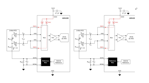
Figure 1: Cutting off the excitation current
When the field current is exchanged, the system designer must wait until the input signal is stable for efficient measurements. The settling time is based on the selected analog-to-digital converter (ADC) and any external filters that have been installed. Switching the multiplexer and waiting to acquire a reading adds delay to the measurement system, which may be undesirable in some applications. As timing becomes more complex, the digital processing algorithms required to convert average results into temperature readings have become increasingly cumbersome.
Three-wire RTD measurement system with high side reference
A more efficient alternative to disconnecting the field current is to place the reference resistor on the high side of the RTD sensor (Figure 2). In this configuration, only one excitation current flows through both the reference resistor and the RTD. The second excitation current is only used for three-wire RTD lead resistance cancellation. Since only one excitation current produces a reference voltage and an input voltage, current source mismatch and mismatch drift will no longer affect the ADC transfer function. Any mismatch error can only affect the effectiveness of the RTD lead cancellation, which is no different from the original circuit.
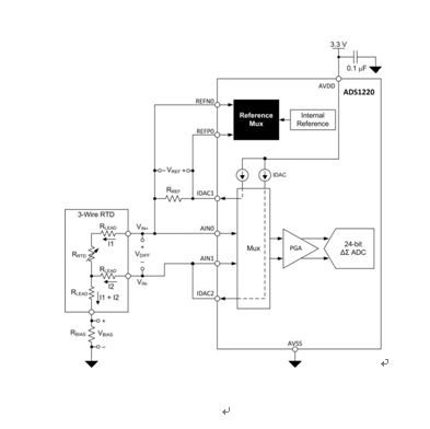
Figure 2: High Side Reference Resistor Configuration
High side reference circuit configuration
By moving the low-side reference resistor to the high side of the RTD, the new configuration introduces additional design challenges. First, an additional resistor RBIAS must be connected from the RTD to ground. The voltage VBIAS across the RBIAS will change the RTD voltage over the linear input common-mode voltage range of the ADC. To achieve this goal, the voltage at the output of the current output digital-to-analog converter (IDAC) must be below its compliance voltage rating.
Equation (1) illustrates the input common mode voltage VCM applicable to the circuit of Figure 2.
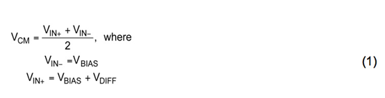
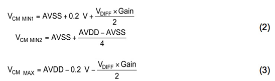
The input common-mode voltage for a programmable gain amplifier (PGA) must be within the range specified in the product specification. Equation (2) shows two limits of the minimum common mode voltage VCM MIN. Please use the larger of the two values ​​VCM MIN. Equation (3) illustrates the maximum common mode voltage VCM MAX.
The voltage at the IDAC output must not exceed the compliance voltage or they will not function properly. Equation (4) illustrates the compliance voltage of the IDAC.

In this circuit configuration, the maximum IDAC output voltage is at IDAC1, represented by VIDAC1 MAX. This voltage at VIDAC1 can be calculated using equation (5).

Based on the 3.3V supply, Table 1 shows the minimum and maximum common-mode voltages as well as the IDAC compliance voltage.
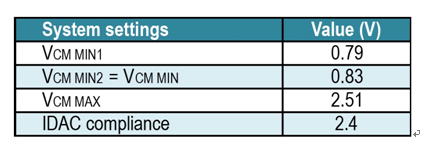
Table 1: Common Mode and IDAC Compliance Voltage Limits Using a +3.3V Supply 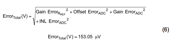
In the high-side reference configuration, the voltage at the IDAC output is increased because RBIAS is added - this reduces the available headroom. To meet IDAC voltage compliance requirements, it may be necessary to reduce the reference or bias voltage by adjusting the IDAC current or resistor value. Conversely, different IDAC currents may need to adjust the PGA gain to maintain system resolution.
With the recommended high-side reference solution, it is still practicable to meet the input common-mode and IDAC compliance voltage limits. First, select a bias voltage that exceeds VCM MIN. This maximizes the margin to meet IDAC compliance voltage requirements. The reference voltage and PGA gain settings are then selected based on the maximum RTD voltage to maximize system resolution.
Table 2 lists the circuit values ​​for a high-side reference circuit that is reasonably optimized using a +3.3V supply. It also lists the VCM MIN and VCM MAX voltages and the VIDAC1 MAX voltage in the circuit. Note that the maximum ADC input voltage can take advantage of most of the VREF voltage range while ensuring that the common mode and IDAC compliance voltage limits listed in Table 1 are not violated.
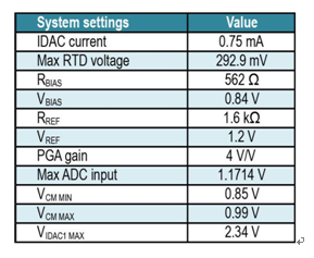
Table 2: Circuit parameters for high side reference circuits
High side reference circuit total error
We analyzed the errors produced by the ADC and RREF. Although the equation and error source remain the same, the input-related voltage error will vary based on the newly selected IDAC current and component values ​​in the circuit. Table 3 summarizes the error sources and calculates the total likelihood error for the high-side reference circuit at 25 °C. As shown, the error from the IDAC mismatch can be eliminated. The total error can be calculated using equation (6).
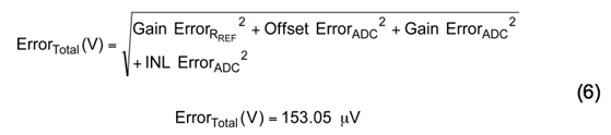
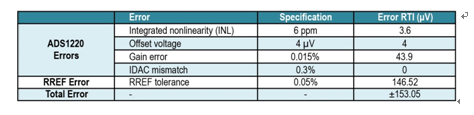
Table 3: Total error (TA = 25 °C).
The total input correlation voltage error can again be converted to a temperature error.
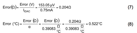
Eliminating the excitation current mismatch error reduces the uncalibrated temperature error by 67% - and the temperature error calculated in the original low-side reference configuration is 1.589 °C.
High side reference circuit drift error
Table 4 lists the temperature drift errors of the ADS1220 over the system operating temperature range (TA = -40°C to +85°C). As shown, the high side reference configuration also eliminates errors caused by IDAC mismatch drift.
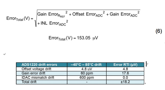
Table 4: Temperature Drift Errors in System Operating Temperature Range (-40°C to +85°C)
The elimination of the error caused by the IDAC mismatch can significantly reduce the input-related drift error (originally 119.6μV, only 18.2μV after the reduction). At present, the total drift error will only produce a temperature error of ±0.062 °C in the temperature range of -40 ° C to 85 ° C; and the total drift error will produce a temperature of ± 0.306 ° C in the low side reference circuit. error. Eliminating errors from field current mismatch reduces the need or requirement for overtemperature calibration.
to sum up
In standard proportional three-wire RTD measurement circuits, the excitation current mismatch is usually the largest source of error, both at room temperature and in the operating temperature range. The cut-off excitation current method is a simple method to reduce the influence of excitation current mismatch in the traditional low-side reference proportional RTD acquisition circuit. The method of changing the circuit to a high-side reference configuration can eliminate the effects of excitation current mismatch and current mismatch drift, while achieving zero measurement delay and minimizing the number of additional components. The high side configuration can also be used for low supply voltages as long as the input common mode voltage and field current compliance voltage limits are specified.
This article highlights two solutions that reduce or eliminate errors caused by IDAC mismatch. It shows how to reconfigure the circuit to a high-side reference circuit so that the effects of field current mismatch and mismatch drift can be completely eliminated with only one additional component.
references
1. Download the ADS1200 product manual.
2. Check out the Precision Hub blog of the TI E2E community, where you can search for related topics, including this one.
Altivar Process ATV900 Drives with embedded services, high performance motor control, safety and application functionality to meet demanding applications including conveyors, cranes, mills and more in the Process Industry. Ideal for segments such as Mining & Metals, Oil & Gas, Food & Beverage and Hoisting. From 0.75kW to 1200kW.
3 Phase Inverter Duty Motor,Frequency Inverter Circuit,Inverter In Ac Drive,Frequency Converter High Power
Wuxi Trenty Machinery & Equipment Co., Ltd. , https://www.elec-inverter.com