In RF applications, directional couplers are used to separate signals based on their direction of propagation. The electric wave induced on the auxiliary arm (coupling line) is proportional to the forward electric wave traveling through the main transmission line. The ratio of the coupled energy to the input energy is referred to as the coupling factor.
Directivity is defined as the difference in energy output at the coupling port when energy is transmitted in the desired direction versus when it is transmitted in the opposite direction. This difference is measured in decibels (dB).
The coupling factor can be calculated using the formula:
**Coupling Factor = 10log (P2/P1)**
where P1 represents the input power and P2 is the coupled power.
Similarly, directivity is given by:
**Directivity = 10log (P2/P2R)**
where P2 is the coupling power for the forward signal, and P2R is the coupling power for the reverse signal (as shown in Figure 1).
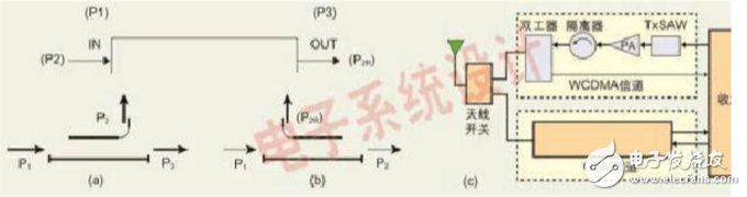
*Figure 1: (a) Forward, (b) Schematic diagram of the reverse directional coupler.*
Another way to express directionality is:
**Directionality (dB) = Isolation (dB) - Coupling (dB)**
Limited isolation directly affects the level of directionality. An energy meter measures the power in a transmission line by detecting the output from a directional coupler at the coupling port. However, this output is influenced by the coupling factor. Reflected signals in the main line can cause measurement errors, known as orientation errors. To improve accuracy, either the reflected signal must be eliminated or a highly directional coupler should be used.
**Energy Control in Mobile Phones**
Mobile phones use an antenna connected to the RF circuitry to both receive and transmit signals (see Figure 2). In the 3G band, WCDMA modulation involves amplifying variable signals. This allows the average output power to reach peak levels, often more than 3 dB, to support a 5 MHz bandwidth shared among 256 users. The base station adjusts the phone’s output power to ensure all uplink signals in the same channel are received within less than 1 dB of accuracy. If not met, call quality may drop, leading to poor user experience.
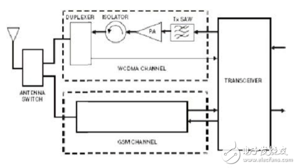
*Figure 2: Basic GSM+3G radio functional block diagram.*
In contrast, the GSM band uses TDMA with GMSK modulation, where each user has exclusive access to a time slot and channel. This minimizes the impact of poor energy control on the network, as it affects other users very little.
**High Directional Coupler Performance**
Changes in a dense antenna environment can lead to impedance mismatches and increased reflected energy. The worst-case VSWR we consider is 6:1, such as when an antenna fails to operate.
To prevent reverse signals from affecting the transmitted signal, an isolator is typically placed between the power amplifier (PA) output and the antenna. The impedance is usually 50 Ω. However, isolators are often removed due to several drawbacks: they are bulky, take up valuable PCB space, are expensive, introduce high insertion loss (typically over 0.7 dB), and are sensitive to temperature changes, aging, and performance degradation.
To address these issues, coupler solutions have been developed for monitoring PA output signals in energy control applications. These couplers can also be used to monitor transmission and emission energy caused by antenna mismatch (Figure 3).
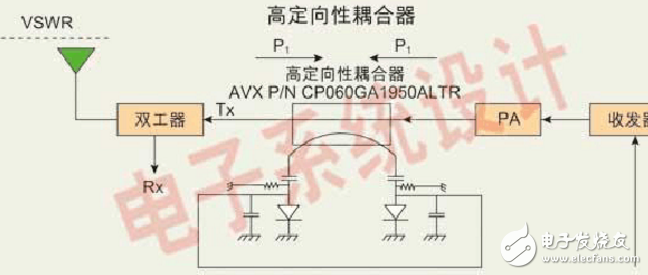
*Figure 3: Under the energy control of a directional coupler.*
Bolier Manometer
Bolier Manometer,Square Pressure Gauge,Square Manometer With Capillary,Square Manometer
ZHOUSHAN JIAERLING METER CO.,LTD , https://www.zsjrlmeter.com