Small DC motor field oriented control allows the drone to enter a higher flight path
Brushless DC (BLDC) motors are widely used in electronic devices such as hard disk drives, cooling fans, and DVD players because of their long life and DC power supply. Typically, the speed and torque of the BLDC are controlled by the MCU using scalar technology.
Nowadays, a new type of application is quietly emerging, among which the four-rotor UAV is the most representative. Such applications are increasingly favored by amateurs. In addition, drones are being monitored and monitored for many commercial applications. Of particular importance for these applications is the dynamic response of the controller and the ability of the controller to smoothly control the BLDC at low speeds and sensorless.
For applications with dynamically changing loads, scalar techniques are not accurate enough. Field Oriented Control (FOC) technology is widely used to drive high-end industrial AC equipment. By implementing FOC, BLDC can provide precise control of drones and other high-performance applications such as medical robots, universal systems, and autonomous vehicles at a reasonable cost.
Designing such products has not been easy in the past. Some of the other advanced advanced motor control technologies, such as FOC or Direct Torque Control (DTC), and the operational knowledge of specialized software development systems are required. If the application is cost sensitive, such as a drone with surveillance cameras that might be used in law enforcement operations, designing affordable BLDC motors will also present challenges.
Field Oriented Control (FOC)The traditional scalar technique used to control BLDC motors is known as six-step (trapezoidal) control. The stator is driven in a six-step process that oscillates at the generated torque. Each pair of windings will be energized until the rotor reaches the next position, at which point the motor will transition to the next step. For sensorless applications, the back EMF generated in the stator windings is typically used to determine the position of the rotor.
The dynamic response of scalar control cannot handle applications where dynamic loads are rapidly changing. As a result, vector control is increasingly being used, from AC motor-driven white goods (such as washing machines) to battery-powered products.
FOC is one of the most common methods of vector control. The working principle is: managing the stator windings to ensure that the magnetic flux generated by the permanent magnets of the rotor is orthogonal to the magnetic field of the stator.
The FOC was originally developed to control three-phase AC motors. Considering that the BLDC power supply for small drones is a 21 V (five-cell lithium polymer battery) battery, the electronic components must contain a low voltage three-phase inverter system. Other major components are motor drivers, MCUs, and software that implements FOC algorithms, where software is probably the most important.
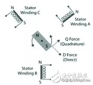
FOC processing is done in the straight-axis (dq) domain, which is a rotating reference frame. The direct axis and the quadrature axis component are the two components of the flux state vector decomposition, that is, the components that generate magnetic flux (d) and torque (q). This relationship is shown in Figure 1. The current in the stator windings of the motor is under control to ensure that the magnetic flux generated by the permanent magnets of the rotor is orthogonal (to 90°) to the magnetic field of the stator. In addition to producing precise motor control, this approach provides extremely accurate torque control, which is the real advantage of operating in the dq coordinate system.
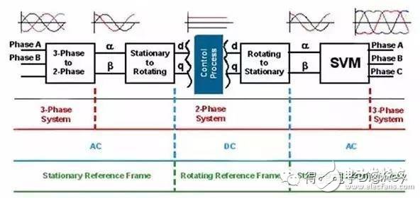
The FOC consists of three domain transformations: (1) the measured phase current in the stator is transformed from a 3-phase stationary coordinate system to a 2-phase stationary coordinate system (α, β); (2) The 2-phase stationary coordinate system is transformed into a rotor flux Aligned rotation binomial coordinate system (dq); (3) In order to actually drive the motor, the dq component is changed back to the stator coordinate system for space vector pulse width modulation (SVPWM). This process is shown in Figure 2.
In order to align the dq coordinate system with the rotor, detailed information on the rotor position is essential. From relatively simple back-EMF zero-crossing detection to complex sliding mode observers and extended Kalman filters, rotor position estimation techniques vary.
motorTransforming from a stationary 3-phase coordinate system to a 2-phase dq coordinate system produces the previously described direct and quadrant components. The straight-axis (d) component has no effective torque, and in fact it tends to increase the bearing wear of the motor. Therefore, one of the goals is to minimize this component. The cross-axis (q) component produces the actual motor torque, which is determined by the application.
The dq component is applied to two PI (proportional-integral) controllers that correspond to zero and applied torque settings to produce a vector output. The output of the two PI controllers is the (new) direct and quadrature voltage components of the desired stator voltage space vector. As mentioned earlier, the final step is to convert the dq component back into the stator coordinate system to actually drive the motor.
The above process is only a summary of the way the FOC works, and many of the rather complex intermediate steps required for its implementation are beyond the scope of this article. For a more detailed FOC discussion directly related to small drones, see the paper "High Performance Motor Control" by Patrick Fisher at the University of Central Queensland, Australia. 1
The intermediate steps required include:
* Determine the characteristics of the motor (except for the number of poles and the voltage and current ratings, BLDC motors rarely provide more nameplate information)
* Estimation of rotor position (key information for implementing FOC control)
* Design a suitable power control solution
* Design torque and speed controller
In general, IC vendors also choose to store their software inventory in the ROM and use it only on selected MCUs to protect their intellectual property.
As mentioned earlier, precise motor control relies on the establishment of a precise motor model. InstaSPIN-FOC includes a proprietary software algorithm called “Observer†that estimates rotor flux, angle, speed and torque (FAST). InstaSPIN-FOC also has motor parameter identification capabilities to extract the necessary performance parameters offline during the development process and to track parameters online during the work process.
Motor parameter information is used to adjust the current control bandwidth.
As a result, designers can have fully fine-tuned sensorless viewing algorithms and fully fine-tuned, stable FOC torque control systems in just a few minutes after starting development. In applications such as propeller control, the only task designers need to do is to test and fine tune the PI speed control single loop to achieve the desired performance and operation.
A simplified version of the basic drive system is shown in Figure 3. The output of the speed PI controller is connected as an input reference signal for the PI current controller. If the speed is too low, the motor will increase the current to produce more torque, which will speed up the speed. Conversely, if the motor is running too fast, the motor will reduce the torque to slow down the speed. Together, the two PI controllers form a cascaded control loop, which means that the control system consists of an external loop with one or more internal loops.
in conclusionA new class of motor control applications is emerging that require excellent dynamic response to small BLDC motors. These applications include medical robots, universal systems, autonomous vehicles and small drones. Although FOC motor control technology has been widely used in AC industrial motors and white goods motors in the past few decades, this technology has not been applied to small motors powered by battery packs because of its complexity and the need for high-performance MCUs. However, in the past few years there have been new products that make this possibility a reality.
Why the Glass wall curtain led display can lead the fashion of outdoor media?
The LED Glass curtain display appeared as an sudden emergence on the outdoor media market.
With the advantages of encapsulation technology, high brightness, wide viewing angle, adjustable screen area and easy installation, The transparent led glass display has gradually replaced the traditional billboards, light boxed, etc., And become the high-profile new force for outdoor advertising media. At the same time, a small pitch is applicable to the glass wall led screen and led glass screen for window. There`re various types of led display products suitable for glass wall and glass window, such as Transparent led display and led strip curtain screen. As if, indoor and outdoor led curtain wall display has become a leading industry for led display market
Led Glass Display,Led Display For Glass Window,Outdoor Transparent Led Display,Glass Wall Led Screen
Shenzhen Priva Tech Co., Ltd. , https://www.privaled.com