The principle and precautions of the relay drive circuit
The relay drive current generally needs 20-40 mA or more, and the coil resistance is 100-200 ohms, so the drive circuit is added. Then what are the principles and precautions of the relay drive circuit?
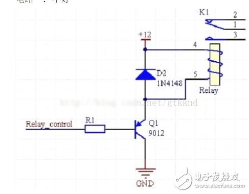
1. The transistor is used to drive the relay and the emitter of the transistor must be grounded.The specific circuit is as follows:
NPN transistor PNP transistor

When the NPN transistor is driven: When the base of the transistor T1 is input to a high level, the transistor is saturated and the collector is turned to a low level, so that the relay coil is energized and the contact RL1 is attracted.
When the base of the transistor T1 is input to a low level, the transistor is turned off, the relay coil is turned off, and the contact RL1 is turned off.
The PNP transistor driver circuit is currently not used and will not be described here.
1.2 The role of each component in the circuit:
Transistor T1 can be regarded as a control switch. Generally, VCBO ≈ VCEO ≥ 24V is selected, and the magnification β is generally selected between 120 and 240. . Resistor R1 mainly acts as a current limiting device, reducing the power consumption of transistor T1 with a resistance of 2 KΩ. Resistor R2 reliably turns off transistor T1 with a resistance of 5.1KΩ. Diode D1 reverses the current and suppresses the surge. Generally, 1N4148 can be selected.
2 integrated circuit 2003 drive relayFigures 1-7 on the left are signal inputs (IN), 10-16 are output signals (OUT), and 8 and 9 are integrated circuit power supplies.
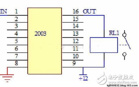

2.1 Introduction to working principle
According to the input and output characteristics of the integrated circuit driver 2003, it is simply referred to as "driver", "reverse", "amplifier", etc., and the commonly used model is now: TD62003AP. When the input terminal of 2003 is high level, the corresponding output port outputs low level, the relay coil is energized, and the relay contacts are closed; when the input end of 2003 is low level, the relay coil is powered off, and the relay contact is disconnected; A diode with reverse freewheeling is integrated internally, so it can be used directly to drive the relay.
2.2 Inspection and evaluation The method of judging whether the quality is good or bad in 2003 is very simple. The input and output voltages are measured separately by the multimeter DC file. If the input terminals 1 to 7 are low level (0V), the output terminals 10 to 16 must be high level (12V). On the contrary, if the input terminals 1 to 7 are high level (5V), the output terminals 10 to 16 must be low level (0V); otherwise, the driver is broken.
Test conditions: 1. Standby; 2. Power on.
Test method: adjust the multimeter to 20V DC file, the negative meter is connected to the ground wire of the electric control board (7812 voltage regulator heat sink), and the positive pen touches each foot of 2003 respectively.
Mv Power Cable,Armor Mv Cable,Steel Tape Armor Cable,Sta Medium Voltage Cable
Baosheng Science&Technology Innovation Co.,Ltd , https://www.bscables.com